Figures & data
Figure 1. Optical design flowchart.
Figure 2. Temperature gradients and thermal fluxes across the parabolic trough solar collector for the thermal analysis.
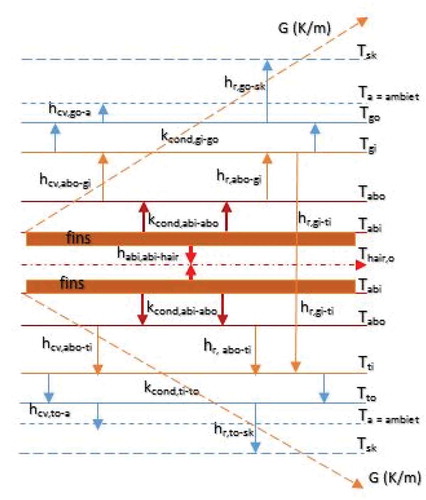
Table 1. Input data to the optical design equations
Table 2. Input data to the thermal design equations
Table 3. Physical characteristics of the parabolic trough solar collector (PTSC)
Table 4. The simulated results of the optical design variables
Table 5. The simulated results of the thermal design variables
Figure 3. Dependency of optical efficiency on the incidence angle.
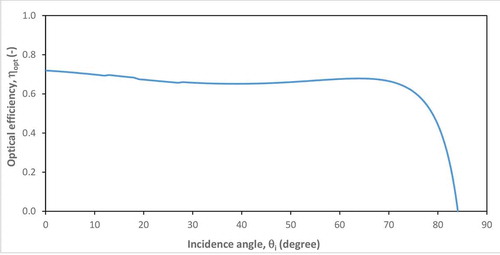
Figure 4. Reliance of optical efficiency on the rim angle and aperture.
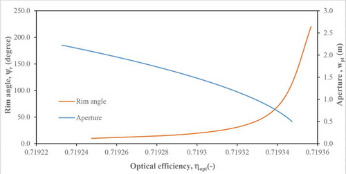
Figure 5. Reliability of optical efficiency on the aperture and height of the trough.
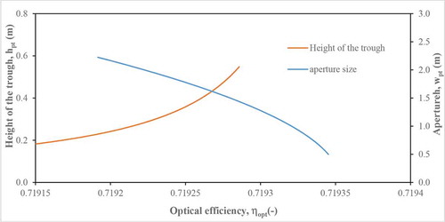
Figure 6. Dependence of optical efficiency on the concentration ratio and absorber outer diameter.
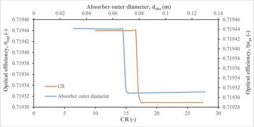
Figure 7. Sensitiveness of concentration ratio of the aperture and absorber sizes.
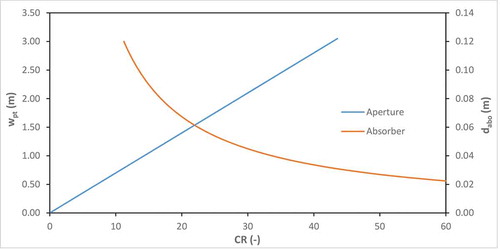
Figure 8. Dependency of rim angle to the focal distance and height of the trough.
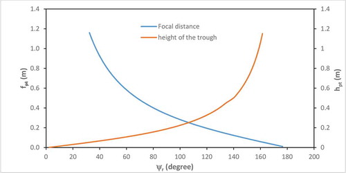
Figure 9. Responsiveness of rim angle of the aperture and focal distance.
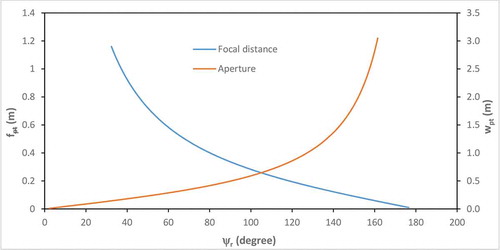
Figure 10. Sensitivity of thermal efficiency on the solar irradiance and aperture area.
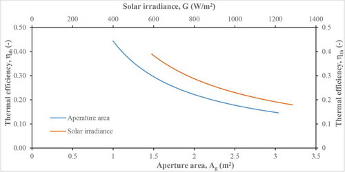
Figure 11. Susceptibility of thermal efficiency on the exit fluid temperature and inlet fluid temperature.
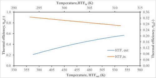
Figure 12. Susceptibleness of thermal efficiency on the absorber inner diameter and HTF velocity.
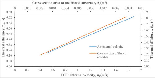
Figure 13. Response of exit fluid temperature on the solar irradiance and aperture area.
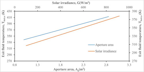
Figure 14. Reaction of exit fluid temperature on the HTF velocity and absorber diameter.
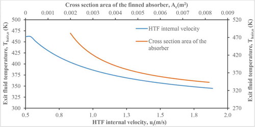
Figure 15. The Effect of concentration ratio and overall heat transfer coefficient on the thermal efficiency.
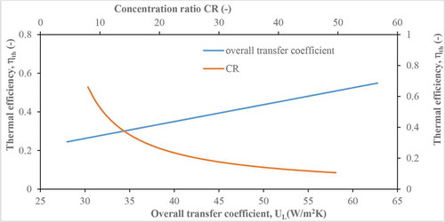
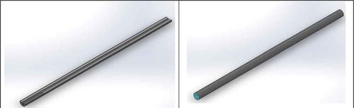
Figure 16. The isometric drawings of the reheating unit.
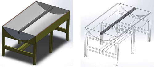
Figure 17. The orthographic and component drawings of the reheating unit.
Figure 18. The detailed support drawing of the reheating unit.
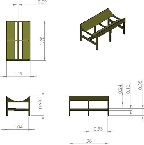
Figure 19. Sectional views of the air-solar-finned absorber.