Figures & data
Figure 1. Block diagram of the proposed adaptive robust proportional integral derivative controller
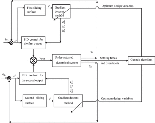
Figure 2. Flowchart of the introduced control method
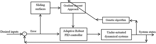
Figure 3. Mechanical structure of the ball-beam system
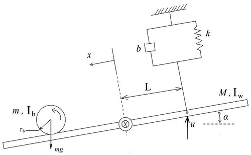
Table 1. The physical specifications of the ball-beam system
Table 2. The optimal values of the control gains for the proposed approach
Table 3. The comparison of the settling times and overshoots for the ball and the beam
Figure 4. Optimization trajectory for the adaptive robust PID control of the ball-beam system
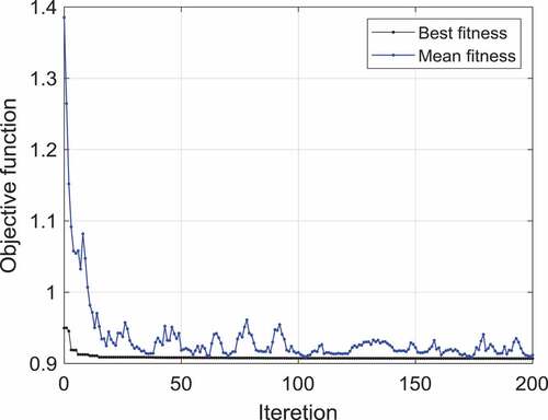
Figure 5. The time behaviors of the proportional gains for the first and second outputs of the ball-beam system
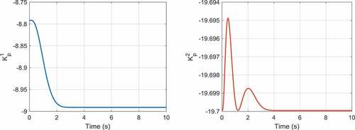
Figure 6. The time behaviors of the integral gains for the first and second outputs of the ball-beam system
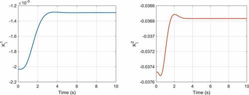
Figure 7. The time behaviors of the derivative gains for the first and second outputs of the ball-beam system
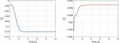
Figure 8. The comparison of the time responses of the ball’s position
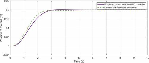
Figure 9. The comparison of the time response of the beam’s angle
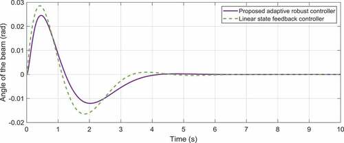
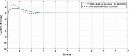
Figure 10. The comparison of the time response of the control effort for the ball-beam system
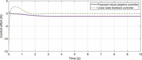
Figure 11. The physical structure of the cart-pole system
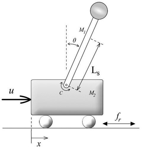
Table 4. The physical characteristics of the cart-pole system
Table 5. The optimum gains of the proposed control approach for the cart-pole system
Table 6. The comparison of the settling times and overshoots for the cart-pole system
Figure 12. Optimization trajectory for the adaptive robust PID control of the cart-pole system
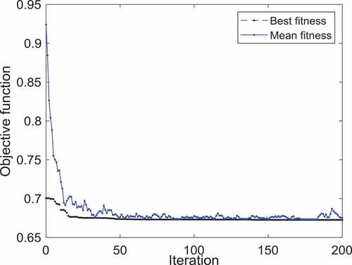
Figure 13. The time behaviors of the proportional gains for the first and second outputs of the cart-pole system
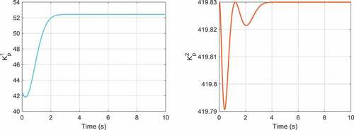
Figure 14. The time behaviors of the integral gains for the first and second outputs of the cart-pole system
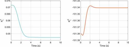
Figure 15. The time behaviors of the derivative gains for the first and second outputs of the cart-pole system
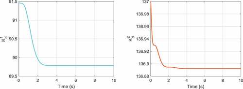
Figure 16. The comparison of the time responses of the cart’s position
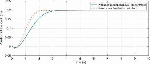
Figure 17. The comparison of the time response of the pole’s angle
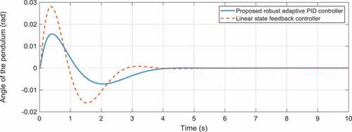
Figure 18. The comparison of the time response of the control effort for the cart-pole system