1,266
Views
0
CrossRef citations to date
0
Altmetric
ELECTRICAL & ELECTRONIC ENGINEERING

Understanding multi-domain compact modeling of light-emitting diodes

ORCID Icon | (Reviewing editor)
Article: 1915730 | Received 05 Jan 2021, Accepted 22 Mar 2021, Published online: 26 Apr 2021

Figures & data

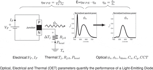
Figure 1. Optical, Electrical and Thermal (OET) parameters are used to quantify the performance of a LED
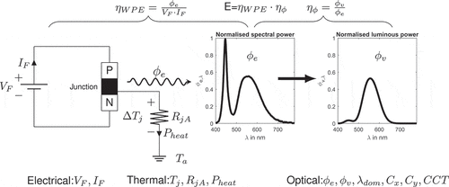
Figure 1. Optical, Electrical and Thermal (OET) parameters are used to quantify the performance of a LED

Figure 2. Mutual dependency of optical, electrical and thermal parameters of a LED luminaire represented in the form of cause and effect representation
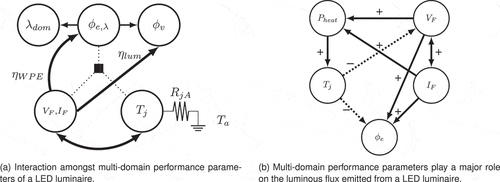
Figure 2. Mutual dependency of optical, electrical and thermal parameters of a LED luminaire represented in the form of cause and effect representation

Figure 3. Exponential nature of VF-IF characteristics, a small change in forward voltage ΔVF creates a large change in forward current ΔIF
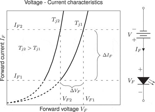
Figure 3. Exponential nature of VF-IF characteristics, a small change in forward voltage ΔVF creates a large change in forward current ΔIF

Figure 4. Linear relationship between forward voltage and junction temperature under constant current conditions
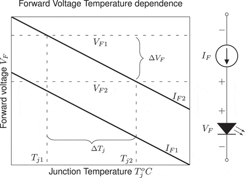
Figure 4. Linear relationship between forward voltage and junction temperature under constant current conditions

Figure 5. Mutual dependency of electrical and thermal characteristics of a LED. Constant forward IF current operation prevents thermal run-away.
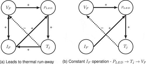
Figure 5. Mutual dependency of electrical and thermal characteristics of a LED. Constant forward IF current operation prevents thermal run-away.

Figure 6. Comparison of LED-driving circuits based on electrical characteristics

Figure 6. Comparison of LED-driving circuits based on electrical characteristics

Figure 7. Electrical characteristics of DURIS P8 GW PUSRA1.PM manufactured by OSRAM represented using piecewise-linear model. the model parameters are extracted from the electrical characteristics and represented in a equivalent circuit
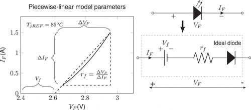
Figure 7. Electrical characteristics of DURIS P8 GW PUSRA1.PM manufactured by OSRAM represented using piecewise-linear model. the model parameters are extracted from the electrical characteristics and represented in a equivalent circuit

Figure 8. Deriving temperature-dependent PWL model of LED from temperature dependence of electrical characteristics
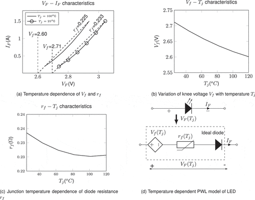
Figure 8. Deriving temperature-dependent PWL model of LED from temperature dependence of electrical characteristics

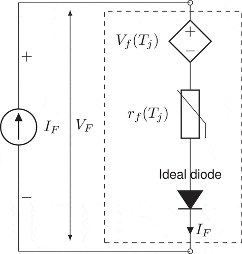
Figure 9. LED equivalent circuit driven by current source, derived from PWL model of electrical characteristics. Approximate electrical equivalent circuit of an LED under forward biased condition (VF>Vf)

Figure 9. LED equivalent circuit driven by current source, derived from PWL model of electrical characteristics. Approximate electrical equivalent circuit of an LED under forward biased condition (VF>Vf)

Figure 10. The constant-voltage-drop model derived from the LED forward characteristics and its equivalent-circuit representation
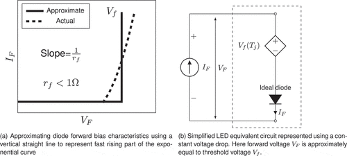
Figure 10. The constant-voltage-drop model derived from the LED forward characteristics and its equivalent-circuit representation

Figure 11. A fraction of electrical power PLED applied to a LED is converted into visible light ϕe and rest needs to be dissipated as waste heat Pheat
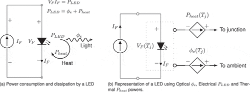
Figure 11. A fraction of electrical power PLED applied to a LED is converted into visible light ϕe and rest needs to be dissipated as waste heat Pheat

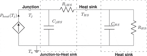
Figure 12. Dynamic thermal model and compact thermal model of an LED mounted on a heat sink. one dimensional heat conduction path from junction-to-ambient in a LED

Figure 12. Dynamic thermal model and compact thermal model of an LED mounted on a heat sink. one dimensional heat conduction path from junction-to-ambient in a LED

Figure 13. Compact thermal model a of LED mounted on a heat sink

Figure 13. Compact thermal model a of LED mounted on a heat sink

Figure 14. Comparison of thermal resistances and effect of aging and degradation on thermal resistance. With aging thermal resistance increases with time
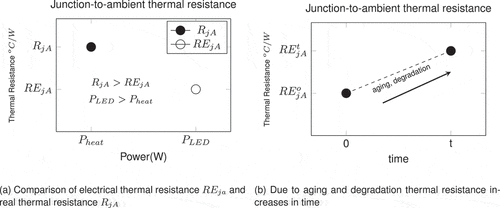
Figure 14. Comparison of thermal resistances and effect of aging and degradation on thermal resistance. With aging thermal resistance increases with time

Table 1. Parameters for multi-domain compact model development for LEDs

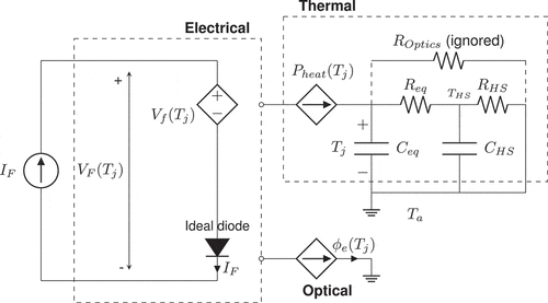
Figure 15. Optical, Electrical and Thermal model of an LED mounted on a heat-sink. this model is represented using single diode rather two parallel diodes as discussed in existing literature

Figure 15. Optical, Electrical and Thermal model of an LED mounted on a heat-sink. this model is represented using single diode rather two parallel diodes as discussed in existing literature