Figures & data
Figure 1. Schematic of the onion slice drying system: 1) Blower, 2) Temperature–relative humidity sensor, 3) Velocity–temperature sensor, 4) Heater, 5) Drying chamber, 6) Valve
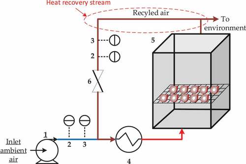
Figure 2. The dimension of onion slice before and after drying
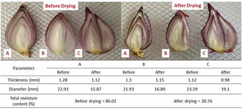
Figure 3. The distribution of hot air along the cross sectional area of the tray dryer
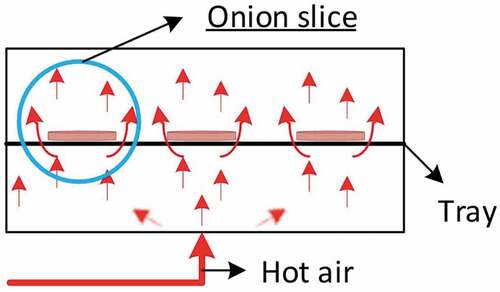
Figure 4. Experimental and modeled moisture ratios as a function of drying time at a drying capacity of 0.1 kg of onion slices (a) without recycled exhaust air, R = 0 and (b) recycled exhaust air to fresh air ratio of 1
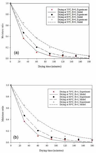
Table 1. Parameter estimations of the Newton model for onion slice drying
Figure 5. Thermal efficiency as a function of drying time under different drying temperatures and drying capacities without recycled exhaust air (R = 0)
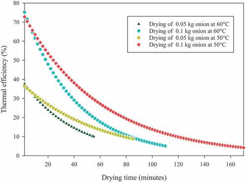
Figure 6. Temperatures of exhaust air at a drying capacity of 0.1 kg of onion slices under different inlet air temperatures without recycled exhaust air (R = 0)
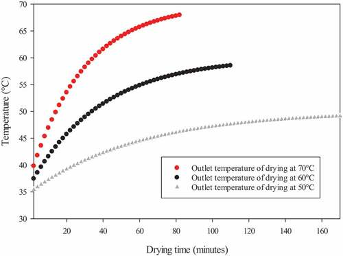
Figure 7. Average thermal efficiency as a function of drying capacity at various drying temperatures without recycled exhaust air (R = 0)
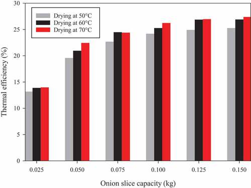
Figure 8. Effect of recycled exhaust air-to-fresh air ratio on the thermal efficiency of onion slice drying at different drying capacities and a drying temperature of 70°C
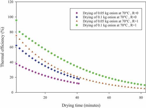
Figure 9. Thermal efficiency of onion slice drying at 70°C at various drying capacities and recycled exhaust air-to-fresh air ratios (R)
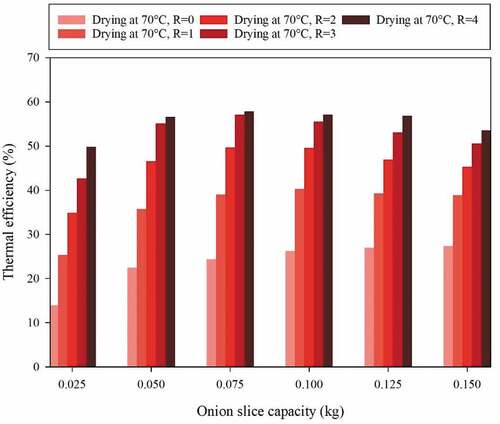
Table 2. Process variables and levels of the orthogonal central composite design
Table 3. Experimental variables used for optimization via the orthogonal central composite design and observed responses of thermal efficiency at a recycled exhaust air-to-fresh air ratio of 4.0
Table 4. Results of the quadratic model of the orthogonal central composite design
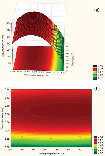
Figure 10. Three-dimensional (a) and two-dimensional (b) plots of the thermal efficiency of onion slice drying