
Figures & data
Figure 1. The general structure of micro-grid and control strategies in it.
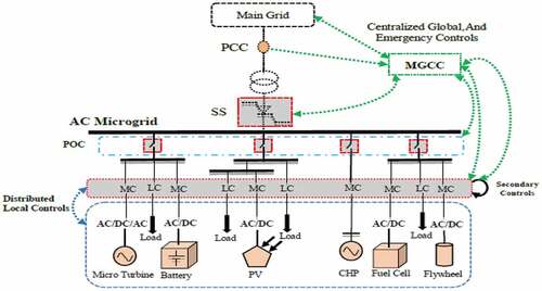
Figure 2. The actual model of the test micro-grid.
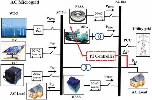
Figure 3. Frequency micro-grid frequency response test model.
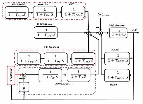
Table 1. The values of the parameters used in the micro-grid frequency model
Table 2. Load values and rated power of scattered products
Table 3. Fuzzy rules
Figure 4. Closed-loop control structure with fuzzy PI-controller-MNHPSO-JTVAC.
Figure 5. Curve of the convergence changes of the algorithm proposed by previous Baroshes.
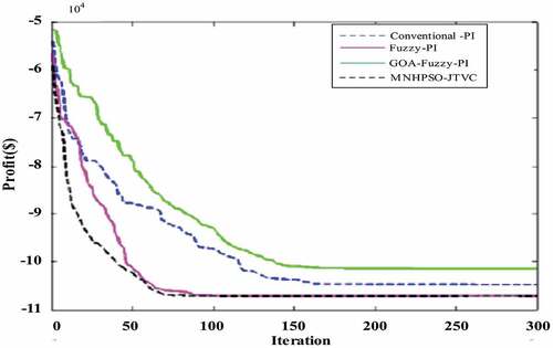
Figure 6. Step load disorders according to p.u
Figure 7. Frequency response of micro-grid to changes in load bridges
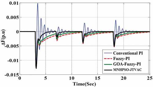
Figure 8. Frequency response of micro-grid to step load changes
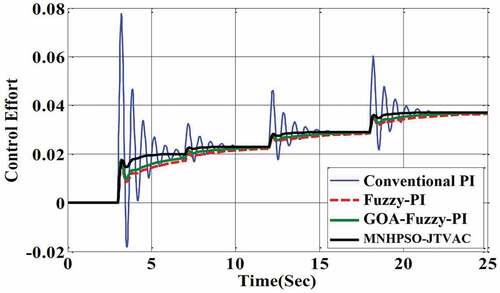
Figure 9. Micro-grid frequency response to load changes of 0.1 p.u.
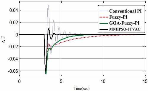
Figure 10. Control attempt for load changes of 0.1 p.u.
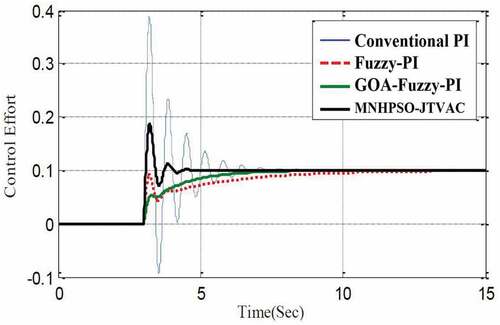
Figure 11. Micro-grid frequency response to changes in its parameters according to Table
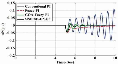
Figure 12. Control attempt for parameter changes according to Table
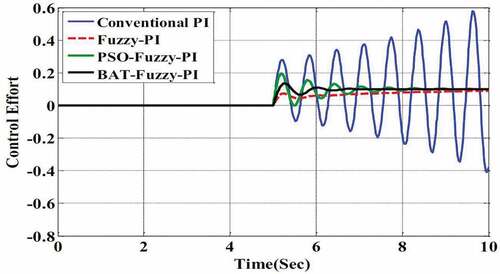
Figure 13. Micro-grid frequency response to changes in its parameters according to Table
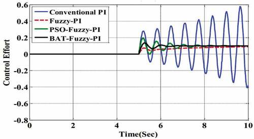
Figure 14. Control attempt for parameter changes according to Table 5
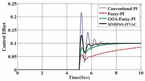
Table 4. Uncertainty of MG parameters in the first scenario
Table 5. The degree of uncertainty of MG parameters in the second scenario
Figure 15. Micro-grid frequency response under the influence of white noise—A) Micro-grid frequency response. B) White noise.
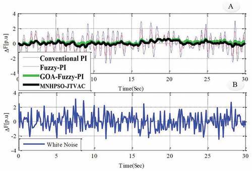
Figure 16. Control noise under the influence of white noise
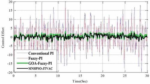
Table 6. Values calculated for the IAE Performance Criterion
Table 7. Values calculated for TV performance criteria
Table