Figures & data
Figure 1. Basic design of the FMM (Hatch et al., Citation2001).
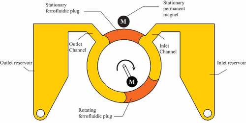
Table 1. Values of and
selected by different investigators
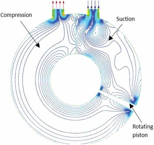
Figure 2. Flow field in the suction/compression chamber.
Figure 3. Comparison of mesh generated for (Mesh A) coarse, (Mesh B) medium, (Mesh C) fine, and (Mesh D) very fine.
Figure 4. Comparison of the numerical results for different mesh sizes.
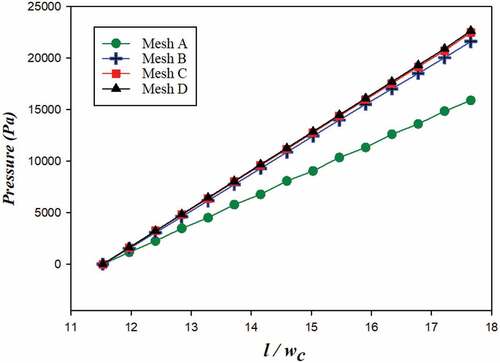
Figure 5. Comparison of first order to second order momentum schemes.
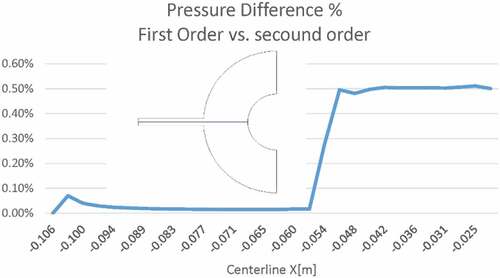
Figure 6. Comparison of the numerical results to analytical solution.
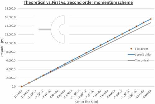
Figure 7. Comparison of the numerical results for different numerical schemes.
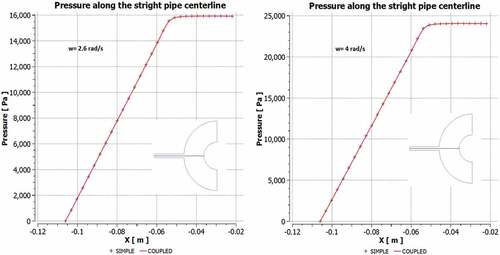
Table 2. Geometric and physical quantities used in the CFD model
Figure 8. CFD pressure contours in the suction chamber.
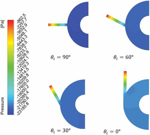
Figure 9. CFD pressure contours in the compression chamber.
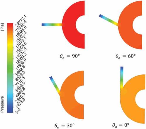
Table 3. Inlet and outlet pressure loss coefficients for different values of inlet and outlet angles
Figure 10. Variation of and
with
and
.
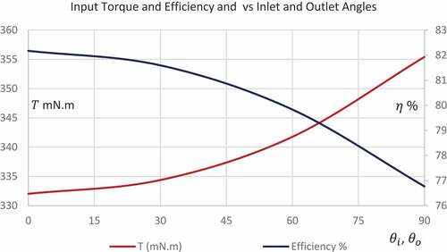
Table 4. Values of ,
,
and
for different values
and
Figure 11. Streamlines in the suction and compression chambers.