Figures & data
Figure 1. Different views of L5-S1 in-silico model, (a) Sagittal view, (b) Posteriolateral view, (c) Anteriolateral view, Transparent vertebrae, and opaque IVD, and ligaments in-silico model of L5-S1 segment (d) Posteriolateral view and (e)Anteriolateral view.
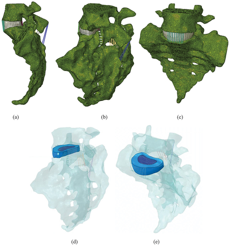
Table 1. Material properties and element types used of the parts involved in the in-silico model
Figure 2. Comparison of three isotropic hyperelastic material models to fit to the experimental results.
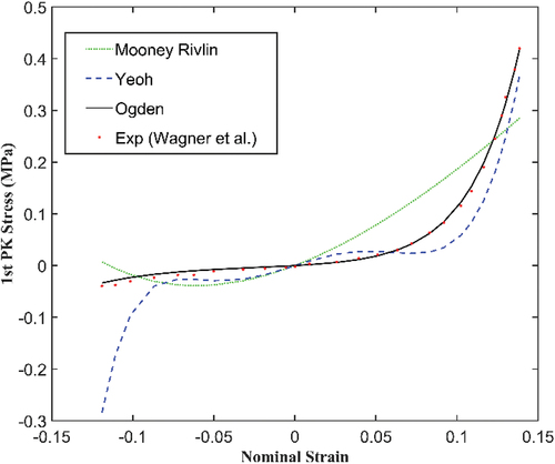
Figure 3. Fibre orientation in the Annulus shown as vectors (a) θ = +30°, (b) θ = −30°.
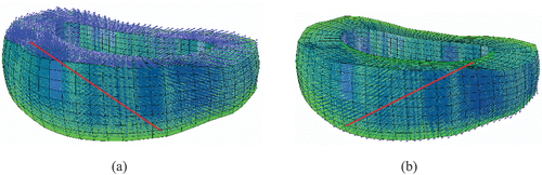
Figure 4. Range of motion plots for, (a) Flexion-Extension movement and (b) Left and Right Lateral movements.
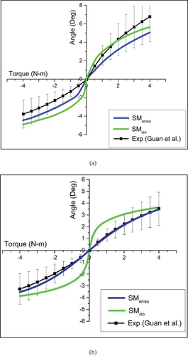
Figure 5. Comparison of facet contact pressure (MPa) for all the considered movements between the two models (FLEX- Flexion, EXT- Extension, LLAT—Left lateral bending, RLAT—Right lateral bending).
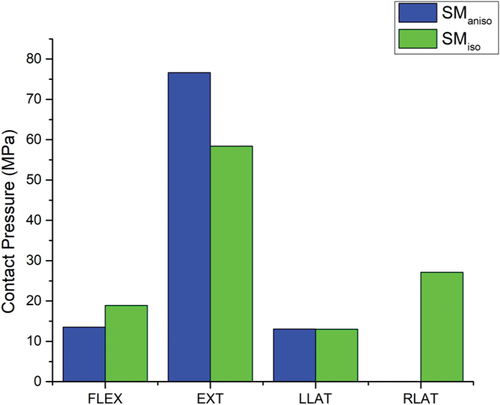
Figure 6. Comparison of maximum von-Mises stress (MPa) on the vertebrae for all the considered movements between the two material models (FLEX- Flexion, EXT- Extension, LLAT—Left lateral bending, RLAT—Right lateral bending).
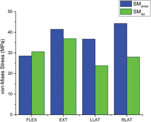
Figure 7. Comparison of ligament strain for all the considered movements between the two models (FLEX- Flexion, EXT- Extension, LLAT—Left lateral bending, RLAT—Right lateral bending).
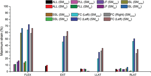
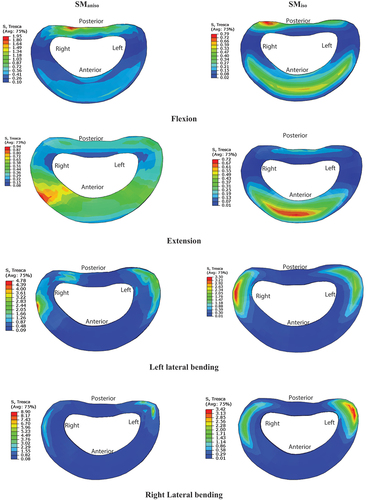
Figure 8. Comparison of maximum shear stresses in midplane of annulus for all the considered movements between the two models.