Figures & data
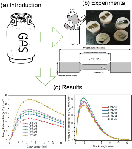
Table 1. Chemical composition of cylinder source materials
Table 2. Material property used for modeling
Figure 1. Optical micrographs of the samples (a) LPG-C1, (b) LPG-C2, (c), LPG-C3, (d) LPG-C4 and (e) LPG-C5.
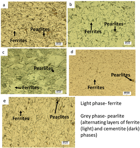
Figure 2. SEM micrographs of the fractured surface showing the ductile behavior of all the samples (a) LPG-C1 (b) LPG-C2, (c) LPG-C3, (d) LPG-C4 and (e) LPG-C5.
Figure 3. Stress-strain curves for various cylinder material sources.
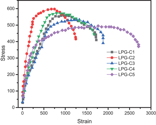
Table 3. Mechanical test results for cylinder sources
Figure 4. Shows the burst testing technique (a) and position of crack relative to welded region in the LPG-C1-LPG-C5 ((b)-(e)).
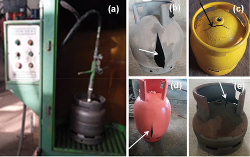
Table 4. Burst test results
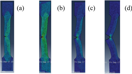
Figure 5. Tensile test models for various cylinder materials (a) LPG-C1 (b) LPG-C2 (c) LPG-C3 (d) LPG-C4 and (e) LPG-C5.
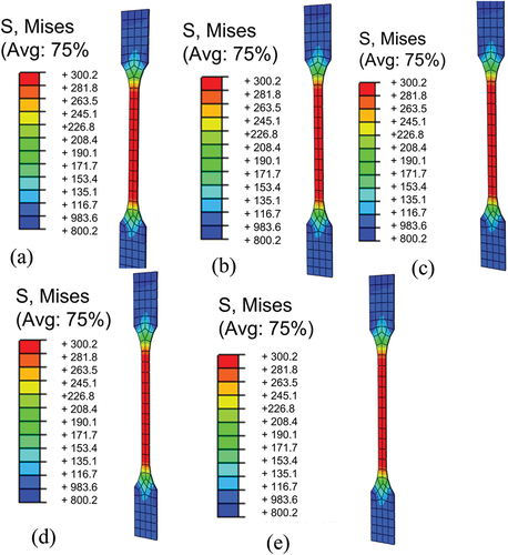
Figure 6. Burst test results for various cylinder material sources (a) LPG-C1, (b) LPG-C2 (c) LPG-C3, (d) LPG-C4 and (e) LPG-C5.
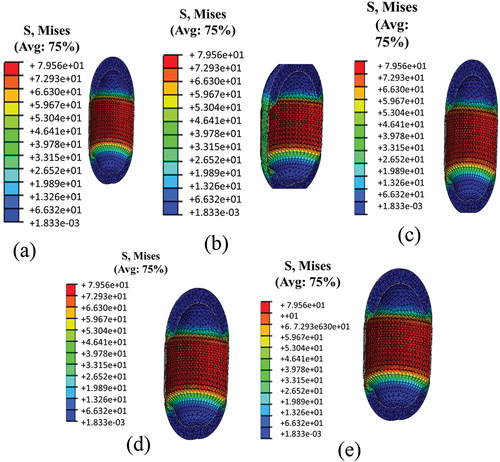
Figure 7. Shows the mechanical properties of samples; (a) fracture toughness and (b) Energy release rate curves.
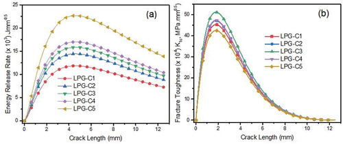
Figure 8. Progression of crack during tensile test of cracked specimen (Models).