
Figures & data
Figure 1. Typical bending test setups: (a) three-point bending and (b) four-point bending.
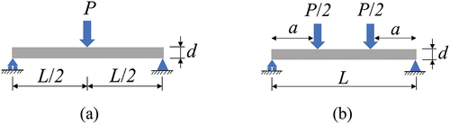
Table 1. Failure modes and associated damage formulae utilised in the Hashin damage model Simulia, (Citation2019)
Figure 2. Three shape functions capturing the structural instability of the I-shape pultruded FRP beam.
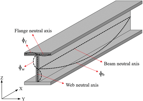
Figure 3. Typical response of shape function weights versus the analysis time: (a) when lateral-torsional buckling is the dominant failure mode, (b) when local buckling is the dominant failure mode, and (c) when web crippling is the dominant failure mode.
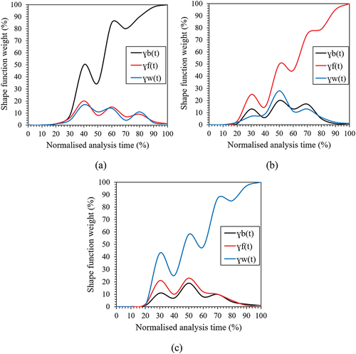
Figure 4. Modelling scheme of variable step size FEM analysis.
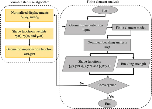
Table 2. Dimensions and test setup details of the validation case studies
Table 3. Characteristic mechanical properties of the I-shape pultruded FRP profiles used in the validation case studies
Figure 5. Experimental versus CVSS-FEM failure modes of the validation case studies: (a) lateral-torsional buckling of I-LTB (experimental photo cited from Nguyen et al. (Citation2014)), (b) web crippling of I-WC (experimental photo cited from Fernandes et al. (Citation2015)), and (c) local buckling of I-LB (experimental photo cited from Yang et al. (Citation2020)).
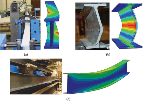
Table 4. Numerical versus experimental and theoretical buckling strength results of the validation case studies of I-shape FRP beams subjected to bending
Figure 6. Solution convergence of the CVSS analysis against default Abaqus/Standard analysis for the validation case studies.
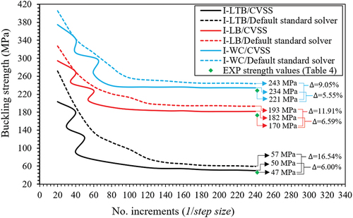
Figure 7. Failure map showing the effect of span-to-depth ratio on I-shape pultruded FRP profiles subjected to three-point bending with different anisotropy ratios.
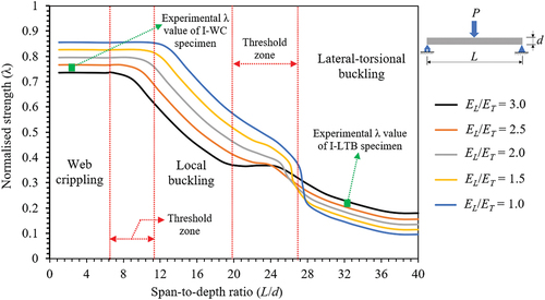
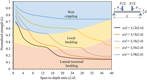
Figure 8. Failure map showing the effect of span-to-depth ratio on I-shape pultruded FRP profiles subjected to four-point bending with different anisotropy ratios ().
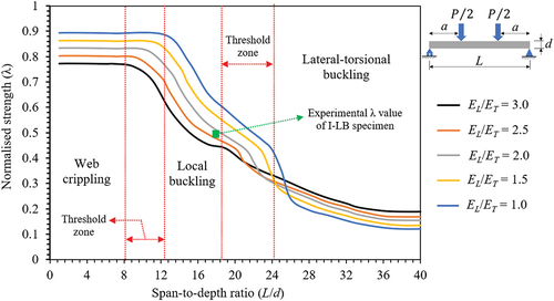
Figure 9. Failure map showing the effect of shear span-to-depth ratio on I-shape pultruded FRP profiles subjected to four-point bending with different anisotropy ratios ().
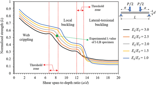
Figure 10. Failure map showing the interaction between the span-to-depth ratio and shear span-to-depth ratio of I-shape pultruded FRP profiles subjected to four-point bending.
Data availability statement
The data presented in this study are available on request from the corresponding author.