Figures & data
Figure 1. Conceptual layout of PTO torque measurement.
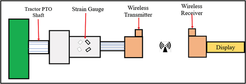
Figure 2. Dynamic simulation of developed torque transducer (a) & (b).
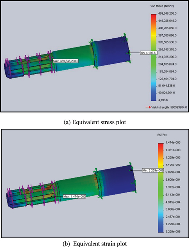
Figure 3. Developed PTO shaft torque transducer.
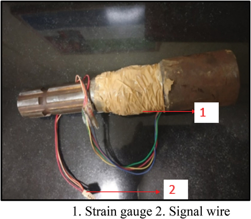
Figure 4. Calibration setup for developed PTO torque transducer.
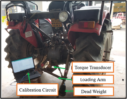
Figure 5. The calibration circuit of the developed PTO torque transducer.
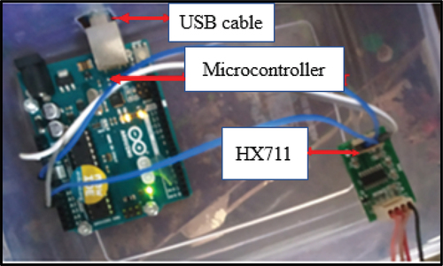
Figure 6. The calibration curve for the developed PTO torque transducer.
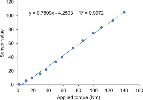
Figure 7. XCTU configuring window for transmitter (a) and receiver Xbee module (b).
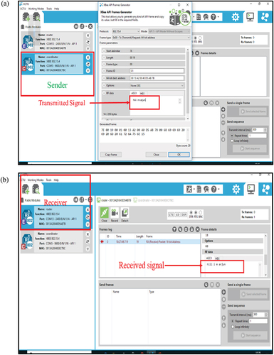
Figure 8. Circuit diagram of signal processing cum transmitting unit.
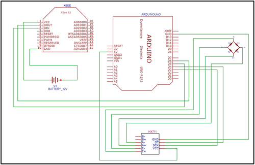
Figure 9. Circuit diagram of receiver cum display unit.
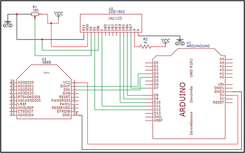
Figure 10. Flow chart of developed PTO torque transducer.
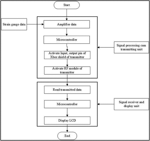
Figure 11. A picture of the setup for speed measurement.
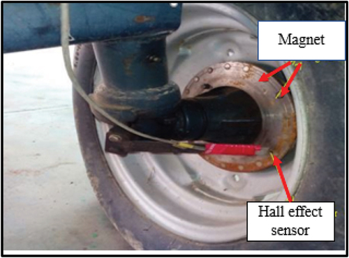
Figure 12. Comparison between calculated torque and observed torque.
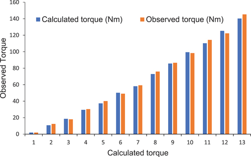
Figure 13. Field testing of developed PTO torque transducer using rotavator.
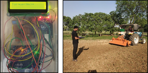
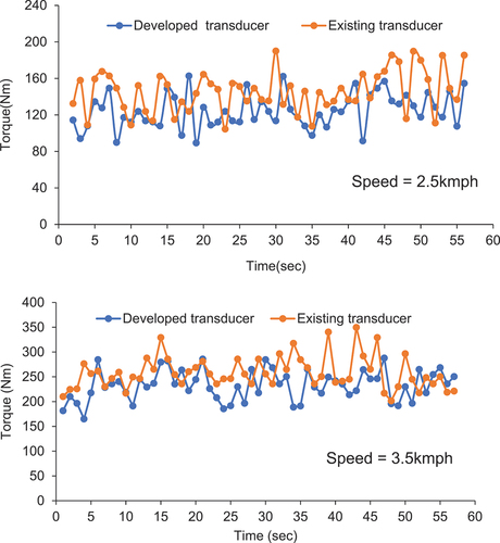
Figure 14. Comparison between observed torque from the developed transducer and existing transducer at 2.5 km/h and 3.5 km/h and at a working depth of 100 mm.