
Figures & data
Table 1. The comparison of the available literature related to EV drivetrain
Figure 1. Schematic diagram of proposed system for EV application.
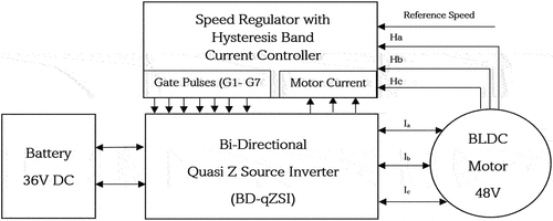
Table 2. Battery parameter specifications (Raghunath, Citation2021)
Table 3. Motor specifications [15]
Table 4. Modes of operation with specified speed, torque and power ratings
Figure 2. BD-qZSI topology.
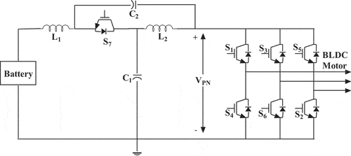
Table 5. Design Calculations of BD-qZSI
Figure 3. (a) Shoot through state and (b) non-shoot through state (Guo et al., Citation2013).
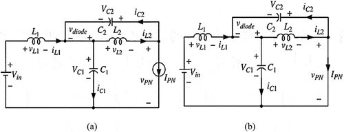
Figure 4. One complete switching cycle of BD-qZSI.
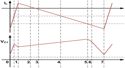
Figure 5. Hysteresis current controller for a BLDC drive.
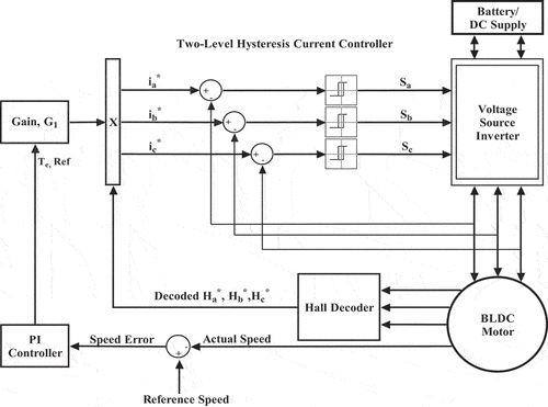
Figure 6. Modified shoot-through hysteresis current controller (STHCC) for a BLDC drive.
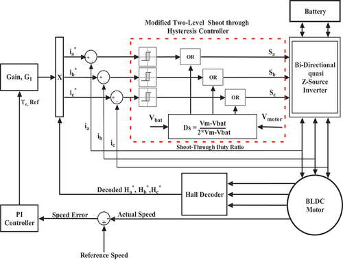
Figure 7. Detailed schematic of the insertion of shoot through into gate pulses.
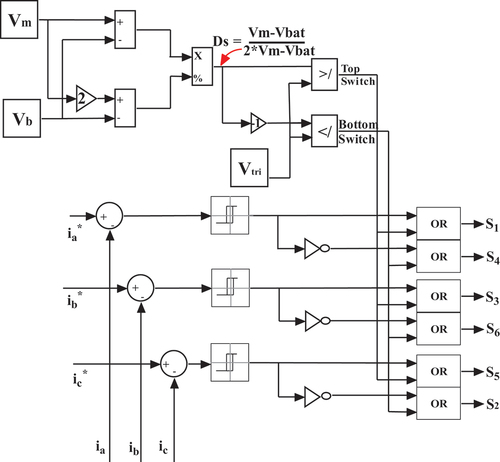
Figure 8. Variation in the state of charge (SoC) level based on operation of the drive.
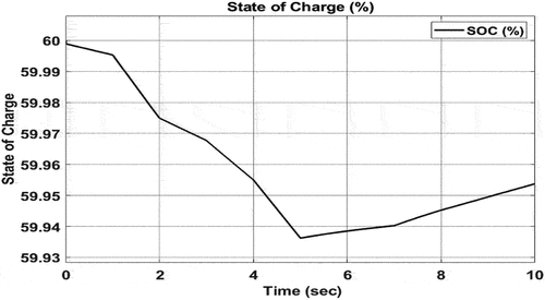
Figure 9. Battery voltage variation different time intervals of the simulation.
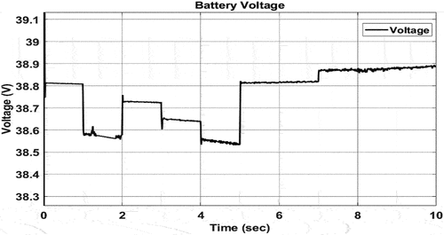
Figure 10. Battery current waveform proportional to the applied torque.
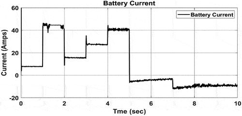
Figure 11. (a) Motor current and (b) motor voltage waveforms established in the BD-qZSI output.
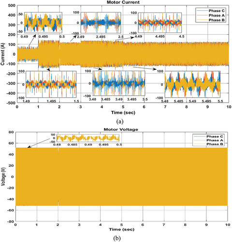
Figure 12. Speed tracking of the motor.
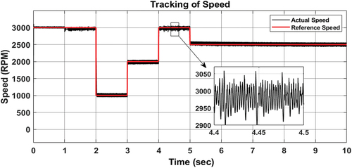
Figure 13. The reference load torque and electromagnetic torque Te in comparison.
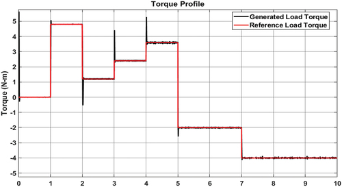
Figure 14. Inductor current across (a) L1 and (b) L2.
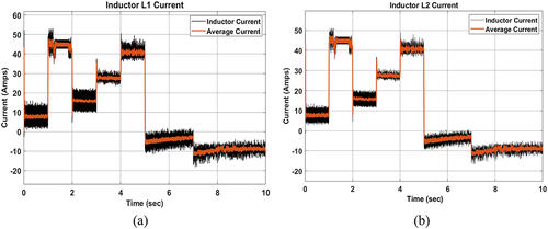
Figure 15. Voltage across (a) capacitor C1 and (b) capacitor C2.
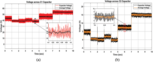
Figure 16. The shoot through switching pulses generated between S2 and S5.
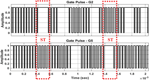
Figure 17. (a) The battery voltage Vbat and motor voltage Vm for reference of STHCC shoot through duty ratio Ds.
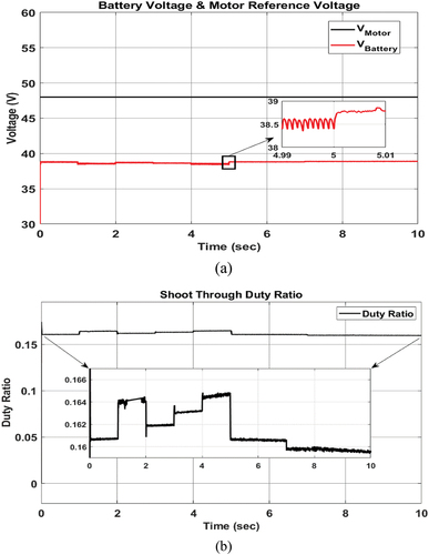
Figure 18. Comparison of (a) reference current and (b) actual current for hysteresis band.
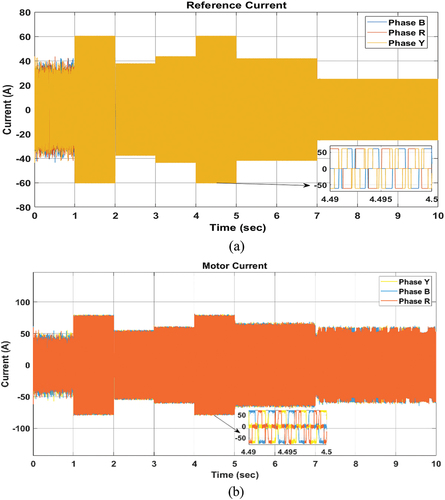
Figure 19. Common mode voltage of the proposed system.
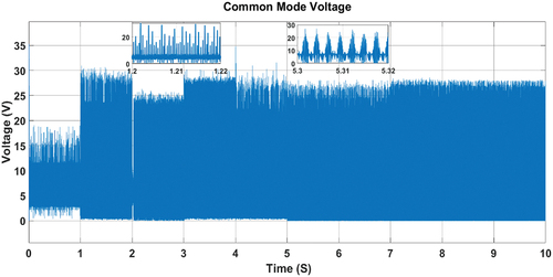
Figure 20. Motoring operation: (a) output power and (b) input power of the motor.
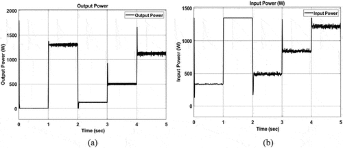
Figure 21. Regenerative braking operation: (a) input power and (b) output power of the motor.

Table 6. Speed and torque ripple at different motor loading