383
Views
0
CrossRef citations to date
0
Altmetric
ELECTRICAL & ELECTRONIC ENGINEERING

Revisiting multi-domain empirical modelling of light-emitting diode luminaire

ORCID Icon &
Article: 2288423 | Received 27 Apr 2021, Accepted 21 Nov 2023, Published online: 14 Dec 2023

Figures & data

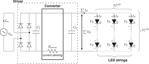
Figure 1. A typical off-line switching LED driver, with electrical capacitances and resistances.

Figure 1. A typical off-line switching LED driver, with electrical capacitances and resistances.

Figure 2. Examples of integrated and non-integrated LED luminaires with points available for measuring electro-thermal characteristics.
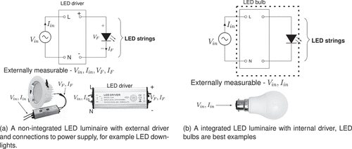
Figure 2. Examples of integrated and non-integrated LED luminaires with points available for measuring electro-thermal characteristics.

Figure 3. Spectral power distribution Φ e,λ of a typical cool white LED bulb with correlated color temperature (CCT) in the range of 5000K–10,000K along with CIE photopic spectral luminous efficiency function V(λ) is shown. Radiant power is weighted by spectral luminous efficiency function to express it photometrically.
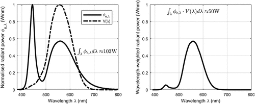
Figure 3. Spectral power distribution Φ e,λ of a typical cool white LED bulb with correlated color temperature (CCT) in the range of 5000K–10,000K along with CIE photopic spectral luminous efficiency function V(λ) is shown. Radiant power is weighted by spectral luminous efficiency function to express it photometrically.

Figure 4. Multi-domain model of a LED luminaire containing ‘N’ identical LEDs mounted on a common heat-sink.
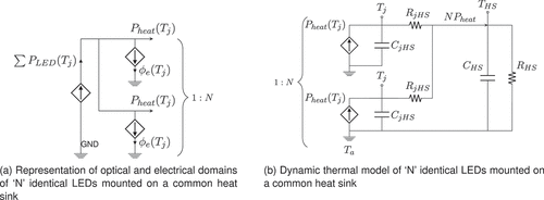
Figure 4. Multi-domain model of a LED luminaire containing ‘N’ identical LEDs mounted on a common heat-sink.

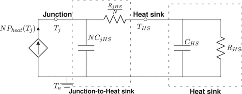
Figure 5. Simplified dynamic thermal model of ‘N’ identical LEDs mounted on a common heat sink.

Figure 5. Simplified dynamic thermal model of ‘N’ identical LEDs mounted on a common heat sink.

Figure 6. Typical non-integrated and integrated LED luminaires.

Figure 6. Typical non-integrated and integrated LED luminaires.

Figure 7. Multi-domain model of non-integrated LED luminaire with the points for measuring OET characteristics. A1,A2 are ammeters and V1,V2 are voltmeters.

Figure 7. Multi-domain model of non-integrated LED luminaire with the points for measuring OET characteristics. A1,A2 are ammeters and V1,V2 are voltmeters.

Figure 8. Multi-domain model of integrated LED luminaire with the points for measuring OET characteristics. A1 is ammeter and V1 is voltmeter.

Figure 8. Multi-domain model of integrated LED luminaire with the points for measuring OET characteristics. A1 is ammeter and V1 is voltmeter.

Figure 9. Thermal RC ladder network representing 1D heat conduction path from the first node (node 1 :junction) to the nth node (node n:Heat sink).
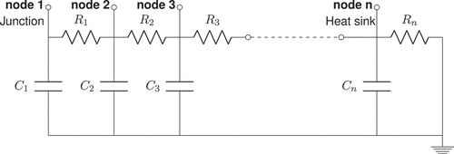
Figure 9. Thermal RC ladder network representing 1D heat conduction path from the first node (node 1 :junction) to the nth node (node n:Heat sink).

Figure 10. The junction temperature Tj, heat sink temperature THS and luminous flux Φ e will exhibit exponential characteristics due to the presence of thermal RC network from junction to ambient. Time constants of these interconnected RC networks is obtained using the Fitted Elmore delay concept.
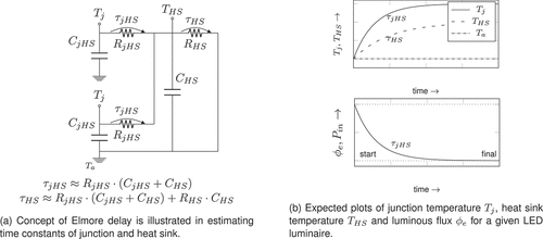
Figure 10. The junction temperature Tj, heat sink temperature THS and luminous flux Φ e will exhibit exponential characteristics due to the presence of thermal RC network from junction to ambient. Time constants of these interconnected RC networks is obtained using the Fitted Elmore delay concept.

Figure 11. Process flowchart depicting the multi-domain empirical modelling of LED luminaires using real-time measurements.
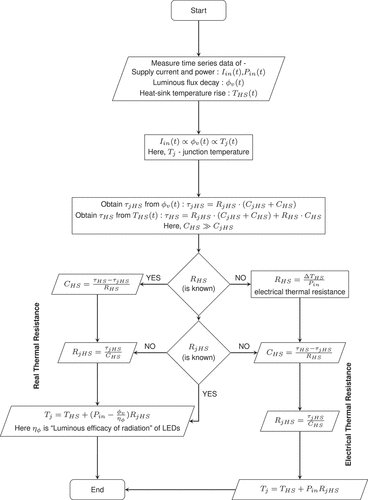
Figure 11. Process flowchart depicting the multi-domain empirical modelling of LED luminaires using real-time measurements.

Figure 12. Measured electro-thermal characteristics of the LED luminaire studied in (Wang, Citation2014). The rise time of chip surface temperature is much faster compared to heat-sink fin temperature. This establishes the fact that junction temperature reaches steady state earlier than heat-sink temperature as proposed in Equationequations (18) and (Equation19). It must be noted that rise time decreases with increased electro-thermal stress.
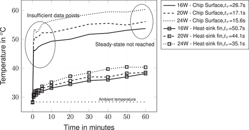
Figure 12. Measured electro-thermal characteristics of the LED luminaire studied in (Wang, Citation2014). The rise time of chip surface temperature is much faster compared to heat-sink fin temperature. This establishes the fact that junction temperature reaches steady state earlier than heat-sink temperature as proposed in Equationequations (18)(18) τjHS≈RjHS⋅(CjHS+CHS)(18) and (Equation19(19) τHS≈RjHS⋅(CjHS+CHS)+RHS⋅CHS(19) ). It must be noted that rise time decreases with increased electro-thermal stress.

Figure 13. Relative spectral power distribution, electro-thermal and opto-thermal characteristics of the LED source used in Baran, Leśko et al. (Citation2019, Baran, Różowicz et al., Citation2019, Citation2020). Electro-thermal characteristics represent power consumption for different forward currents at different junction temperatures. Opto-thermal characteristics represent light output for different drive currents at different junction temperatures.

Figure 13. Relative spectral power distribution, electro-thermal and opto-thermal characteristics of the LED source used in Baran, Leśko et al. (Citation2019, Baran, Różowicz et al., Citation2019, Citation2020). Electro-thermal characteristics represent power consumption for different forward currents at different junction temperatures. Opto-thermal characteristics represent light output for different drive currents at different junction temperatures.

Figure 14. Measured temperatures on the MCPCB (measured closer to the LED junction) and heat-sink fin. It is observed that rise times for both MCPCB and heat-sink fin temperatures are almost same. The derived thermal model of the LED luminiare is shown. This model was obtained using the experimental and simulation data available in (Baran et al., Citation2020). The transient temperature plot and thermal model is already discussed theoretically and shown in Figure .
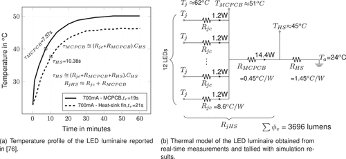
Figure 14. Measured temperatures on the MCPCB (measured closer to the LED junction) and heat-sink fin. It is observed that rise times for both MCPCB and heat-sink fin temperatures are almost same. The derived thermal model of the LED luminiare is shown. This model was obtained using the experimental and simulation data available in (Baran et al., Citation2020). The transient temperature plot and thermal model is already discussed theoretically and shown in Figure 10.
Supplemental material

cover-image-main.tex

Download Latex File (2.9 KB)