
Figures & data
Figure 1. The spectrum of electromagnetic radiation, corresponding sources, and devices (Jagadeesh Chandra et al., Citation2019).
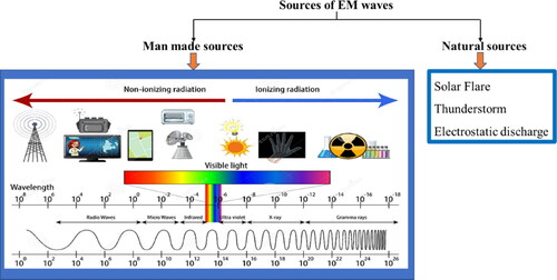
Figure 2. EM Wave motion in a shielding material (Ganguly et al., Citation2018).
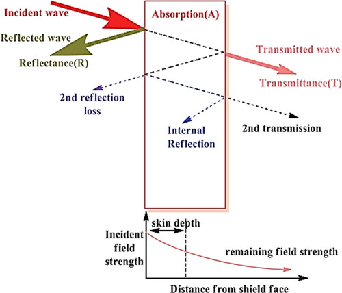
Table 1. Typical CFRP aerospace components are formed by several techniques (Dutton et al., 2014).
Figure 3. Manufacturing flow chart to develop CFRP composites for EM shielding applications.
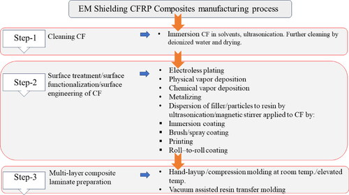
Figure 4. Ni-CF/E composite manufacturing steps (Zhu et al., Citation2021).
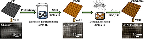
Figure 5. Schematic for the fabrication of the PU-AgNW/CFF fabric (Jia et al., Citation2019).
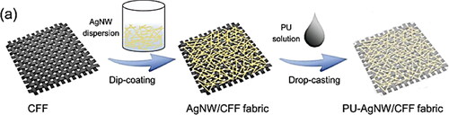
Figure 6. The schematic diagram represents the process steps of CF/Ti3C2Tx MXene/PEEK nanocomposites.
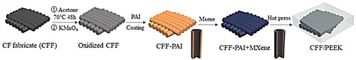
Figure 7. Schematic representation of the preparation process of the hybrid carbon ink‑loaded polyester nonwoven fabric/epoxy composites (S‑x/G/PF/Ep).
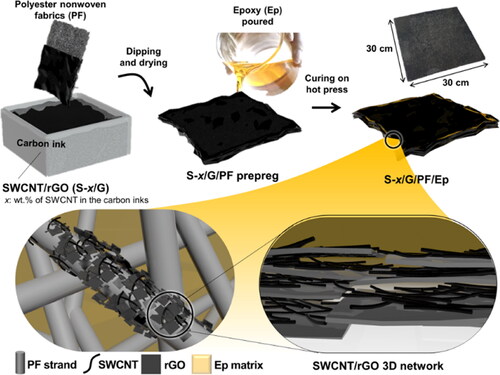
Figure 8. Schematic of the wet electro-flocking method.
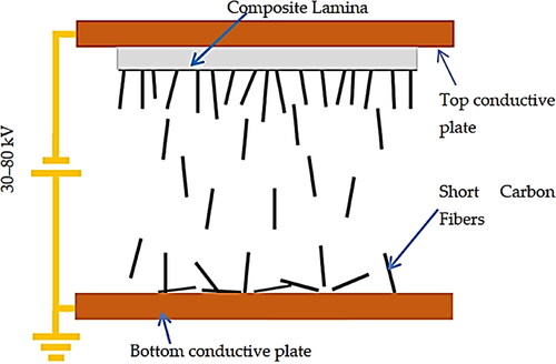
Figure 9. Factors influencing EM wave shielding effectiveness and structure properties of CFRP multilayer laminates.
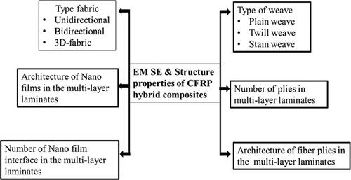
Figure 10. Plot of electromagnetic shielding effectiveness achieved by the various researchers.
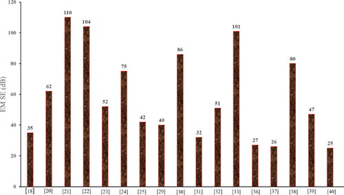
Table 2. The manufacturing method, material combination, conductivity, and shielding effectiveness of CFRP composites.
Data availability statement
All data used for this research is included in this manuscript.