
Figures & data
Table 1. Parameters of Archimedes screw for different number of blades (Rorres, Citation2000).
Table 2. The screw geometry external parameters at L = 1 m, Q = 0.01 m3/s and inclination angle of 300.
Table 3. Hydraulic power of flowing water for range of flow rate and heads.
Figure 1. 3D model of (a) single blade, (b) double blade, and (c) triple blade screw turbines.
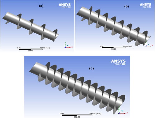
Figure 2. Screw enclosure (a) and mesh generation (b).
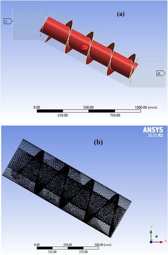
Figure 3. Mesh sensitivity analysis.
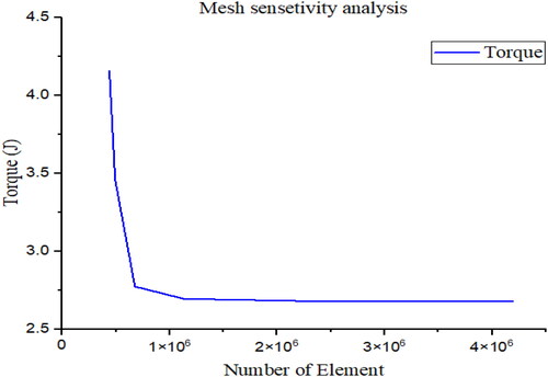
Figure 4. ANSYS CFD modeling of single blade turbine (a) streamline of the flow, and (b) pressure distributions contour over the turbine length.
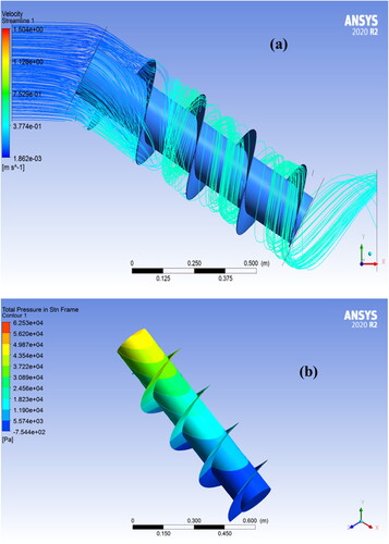
Figure 5. The power output of single blade turbine (a) at a flow rate of 0.01 m3/s, (b) at a flow rate of 0.015 m3/s, and (c) at a flow rate of 0.02 m3/s for different angle of inclination and head.
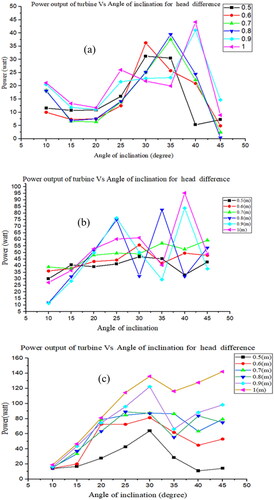
Figure 6. The streamline for (a) two blades turbine and (b) three blades turbine.
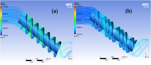
Figure 7. The pressure distributions for (a) two blades turbine and (b) three blades turbine.
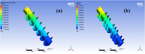
Figure 8. The effect number of blades on the power output of turbine at different angle of inclination.
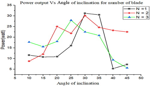
Table 4. Input parameters for the response surface optimization at a flow rate of 0.015 m3/s, a head of 0.7 m, and a rotational speed of 104 rpm.
Figure 9. The effect of inner radius on the power output at a flow rate of 0.015 m3/s, a head of 0.7 m, and a rotational speed of 104 rpm.
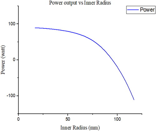
Figure 10. The effect of pitch of screw on the power output at a flow rate of 0.015 m3/s, a head of 0.7 m, and a rotational speed of 104 rpm.
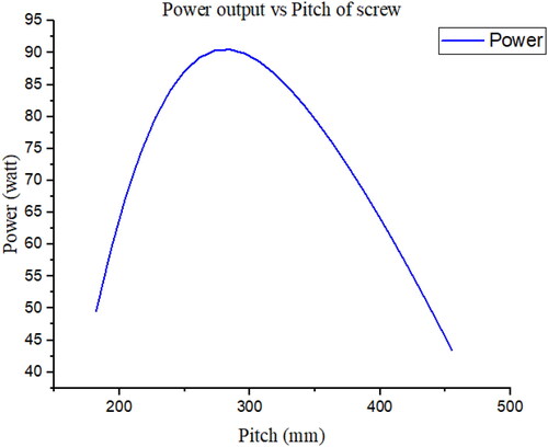
Figure 11. The combined effects of inner radius and pitch of screw on the power output at a flow rate of 0.015 m3/s, a head of 0.7 m, and a rotational speed of 104 rpm by using ANSYS Workbench RSO.
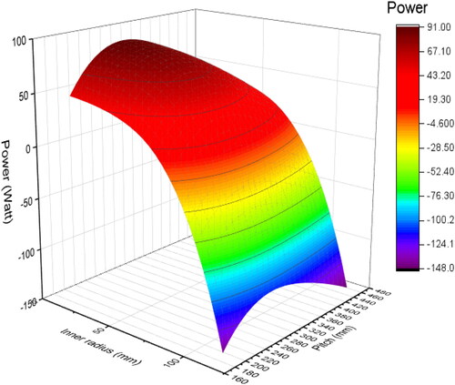
Figure 12. The combined effects of inner radius and pitch of screw on the torque output at a flow rate of 0.015 m3/s, a head of 0.7 m, and a rotational speed of 104 rpm by using ANSYS Workbench RSO.
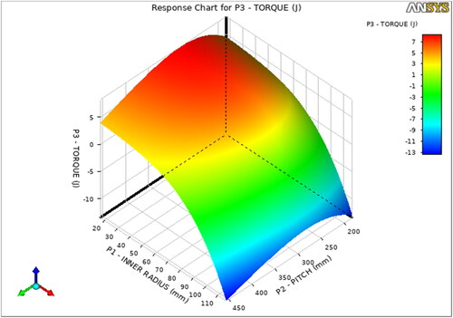
Figure 13. The comparison of the final power output of the reference and optimized screw turbine geometry corresponding to the standard heads of micro-hydropower turbine.
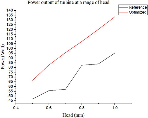
Table 5. Comparison of the initial and optimal design parameters of screw turbine.
Table 6. Comparison of the power output and efficiency of the reference and optimized screw turbine geometry.
Data availability
The data supporting this research work is available on reasonable request from the corresponding author.