
Figures & data
Figure 1. The network architecture of Single-Shot Multibox Detector (SSD) with the MobileNet backbone.
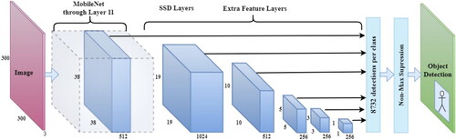
Figure 2. Illustration of the overall methodology and research strategy.
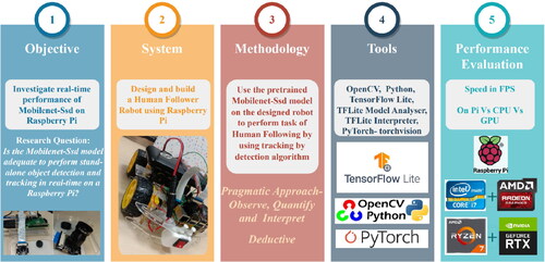
Figure 3. Experiment design depicting independent, dependent, and control variables in the system.
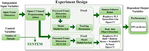
Figure 4. Variable relationship when using TensorFlow support: experiment design 1 (note: controlled/fixed variables have been set to neutralize their effect on the observed variable to provide a fair comparison across trials).
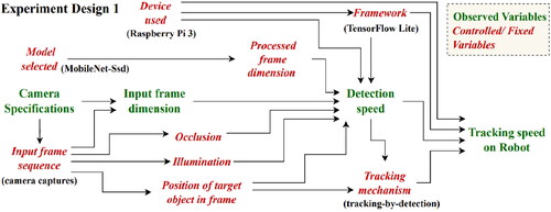
Figure 5. Variable relationship when using PyTorch support: experiment design 2 (note: because the Pi 3 was insufficient to run PyTorch, the device was updated to the Pi 4. PyTorch also lacked an onboard interpreter, which is necessary for tracking).
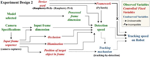
Figure 6. Video comparison.
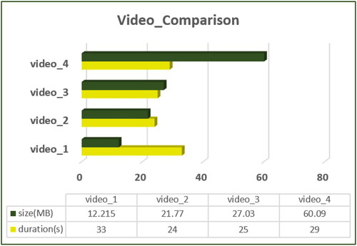
Figure 7. Modular design: depicting the interactions between the processing module, the controller module, and the object detection and tracking module.
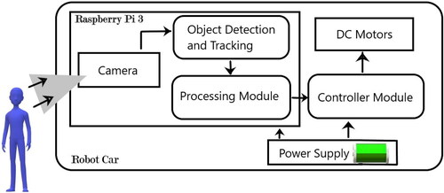
Figure 8. System design and component requirements.
Figure 9. Schematic diagram - human follower robot, depicting the physical connections between the GPIO pins of the Raspberry Pi board, the L298N H-Bridge, the DC motors, and the battery.
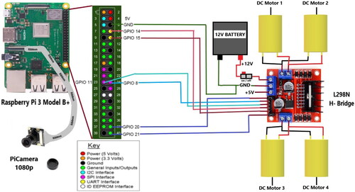
Figure 10. Design of the robot view; the center of the frame has a box defined by the threshold, the status of the robot is displayed in the top right corner, and the speed in FPS is displayed in the top left corner.
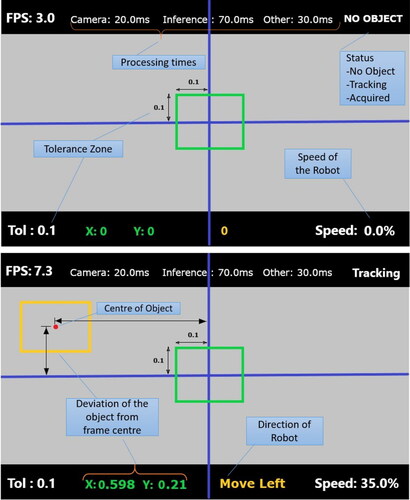
Figure 11. State transition diagram; ‘start’ and ‘stop’ refer to the begin and end of frames, ‘no object’ and ‘acquired’ states cause the robot to stop, and ‘tracking’ state causes the robot to move and follow the human.
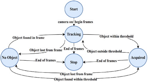
Figure 12. MobileNet-Ssd quantized model memory usage plotted using the TFLite Model analyzer.
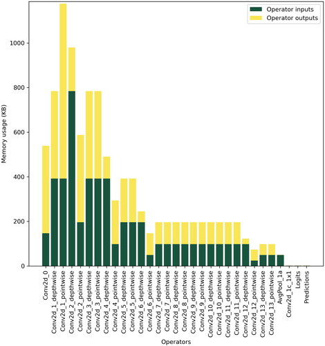
Figure 13. MobileNet-Ssd quantized model tensor information obtained through TFLite Model analyzer.
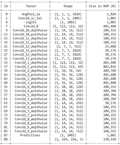
Figure 14. Snapshots of the robot during real-time testing.
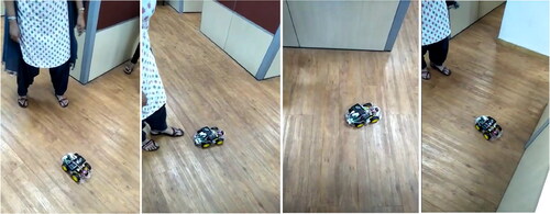
Figure 15. Sample frames of the robot view tested on Video_1 and Video_2.
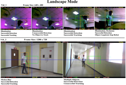
Figure 16. Sample frames of the robot view tested on Video_3.
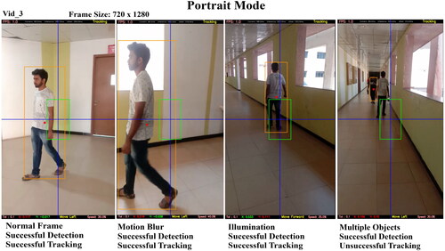
Figure 17. Sample frames of the robot view tested on Video_4.
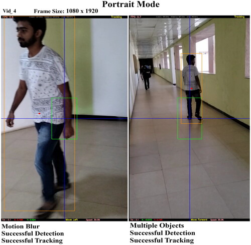
Figure 18. A graph showing how overall speed and iterations are related across the devices.
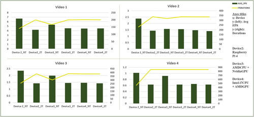
Figure 19. FPS fluctuation recorded on Raspberry Pi 4.
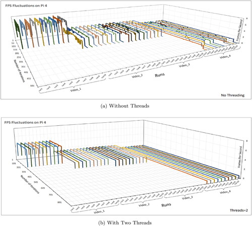
Figure 20. Performance comparisons.
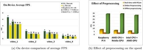
Figure 21. State-of-the-art model comparisons of detection speed in FPS on a Raspberry Pi 4.
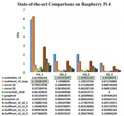
Figure 22. State-of-the-art model comparisons of detection speed in FPS across all the devices for the Pi camera feed.
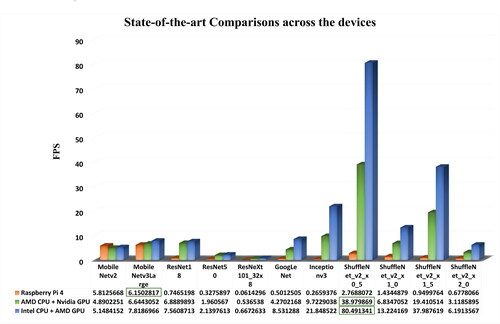
Table A1. Device specifications.
Table 1. Input data: videos captured for the experiment.
Table 2. Tracking results obtained for the different input video sequences.
Table 3. Full factorial design table recording FPS using PyTorch.
Table 4. Full factorial design table recording number of iterations per video using PyTorch.
Table 5. Summary of observations.
apacite.bst
Download (137.8 KB)interacttfqsample.tex
Download Latex File (74.5 KB)references.bib
Download Bibliographical Database File (19.7 KB)interact.cls
Download (23.9 KB)apacite.sty
Download (70.5 KB)Data availability statement
The data, metadata and codes used in this research work will be made available upon reasonable request to the corresponding author’s email-id.