
Figures & data
Table 1. Eco-design approaches developed and applied in PE design research (Fang and Romano et al., Citation2023).
Table 2. Profiles of interviewees (adapted from [Fang et al., Citation2023]).
Figure 1. Generic product development process of power electronics converters.
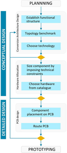
Figure 2. Topology circuit diagram (example of a boost converter).
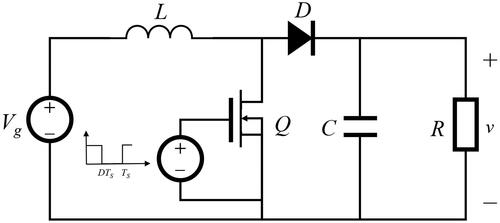
Figure 3. Deliverable of hardware selection (Example of a boost converter).
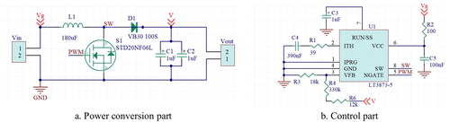
Figure 4. Deliverable of 3D routing (Example of a boost converter).
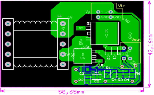
Table 3. Requirements for ecodesign support for integrating the specific ecodesign working and decision-making steps to the PCB-based PEC PDP.
Figure 5. FB-LCA model architecture proposed in this research.
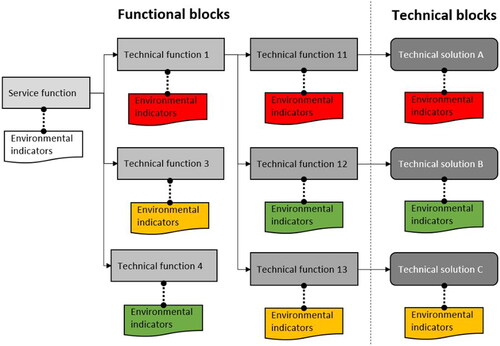
Table 4. Parameters in Block Definition Diagram proposed in the FB-LCA parametric model developed.
Figure 6. Ecodesign application method for PCB-based PEC.
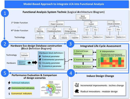
Figure 7. Functional requirement of the boost converter.
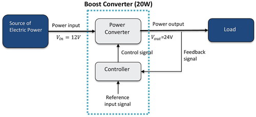
Figure 8. FAST analysis of the boost converter.
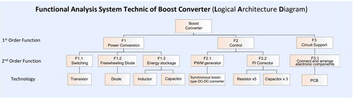
Table 5. Example of hardware ecodesign database content (block definition diagram).
Figure 9. Heat map representation of manufacturing environmental impact tracking in converter’s functional structure.

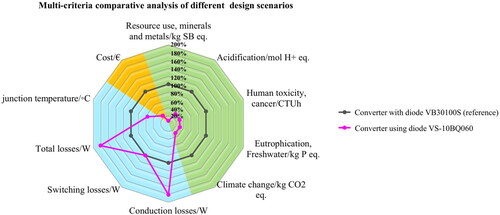
Figure 10. Example of systematic evaluation of design changes during PDP iterations.
Supplementary Material.docx
Download MS Word (90.2 KB)Data availability statement
The authors confirm that the data supporting the findings of this study are available within the article and its supplementary materials. The corresponding author, Li Fang, agree to share the data upon reasonable request.