
Figures & data
Figure 1. Overall structure diagram of circular furrow fertilization device in Mountain orchard.
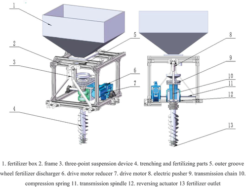
Figure 2. Working principle diagram.
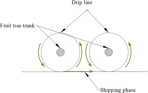
Figure 3. Spiral blade curve type.
Figure 4. Schematic diagram of spiral blade curve structure.
Figure 5. Segmented spiral blade structure and arrangement.

Figure 6. Stress analysis of spiral blade during operation.
Figure 7. Soil cutting amount per revolution of cutter.
Figure 8. Type of embedded blade.
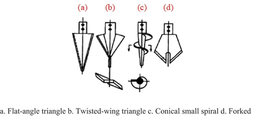
Figure 9. Structure diagram of embedded blade (unit: mm).
Figure 10. Soil particle model.
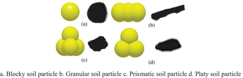
Figure 11. Soil simulation model.
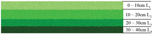
Table 1. Spatial location parameters of each model
Table 2. Parameters of soil simulation model
Table 3. Single factor comparative simulation test scheme
Figure 12. Comparison diagram of simulation model.
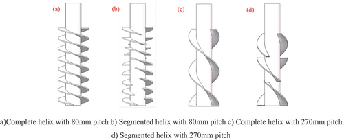
Figure 13. Simulation model of vertical spiral trenching.
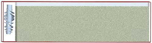
Table 4. Steel related simulation parameters
Figure 14. Effect of factor interactions on operating moments.
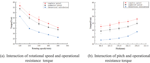
Figure 15. Interaction of factors on soil particles.
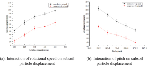
Figure 16. Discrete element simulation model of trenching and fertilizing parts.
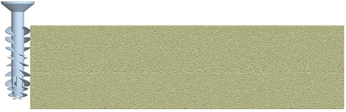
Table 5. Orthogonal simulation test scheme and results
Figure 17. Particle statistical extraction process.
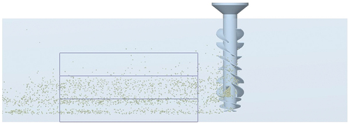
Figure 18. Influence trend of interaction items.
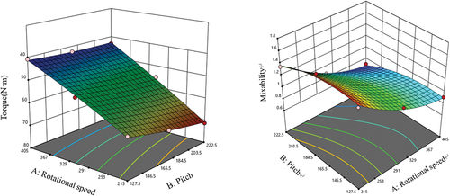
Table 6. Analysis of variance of resistance torque regression model