1,334
Views
8
CrossRef citations to date
0
Altmetric
Research Article

High-pressure and high-temperature synthesis of rhenium carbide using rhenium and nanoscale amorphous two-dimensional carbon nitrideFootnote1

, , , , , , , , & | (Reviewing Editor) show all
Article: 1076702 | Received 25 Mar 2015, Accepted 17 Jun 2015, Published online: 07 Sep 2015

Figures & data

Table 1. Compilation of experimental bulk moduli reported so far

Figure 1. (a) Cross-sectional view of synthesized sample that looks like cloud in Pt capsule (white). Dark smooth part in white-grey sample is epoxy resin. Scale bar at bottom right is 100 μm. Initial outer diameter of Pt capsule is 2 mm, and it is about 3 mm in height. (b) Magnified SEM photograph.
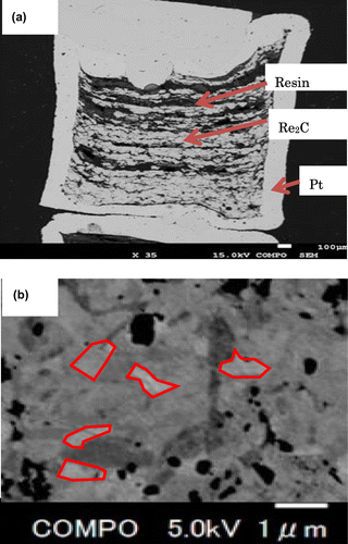
Figure 1. (a) Cross-sectional view of synthesized sample that looks like cloud in Pt capsule (white). Dark smooth part in white-grey sample is epoxy resin. Scale bar at bottom right is 100 μm. Initial outer diameter of Pt capsule is 2 mm, and it is about 3 mm in height. (b) Magnified SEM photograph.

Figure 2. Measured EDS signals of synthesized sample. Re and C, and small amount of N and O were detected.
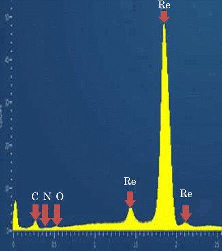
Figure 2. Measured EDS signals of synthesized sample. Re and C, and small amount of N and O were detected.

Table 2. Composition of synthesized Re compound

Figure 3. Raman spectra of synthesized sample.
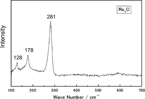
Note: Laser spot (1 μm) for measurement is small enough in comparison with synthesized sample area.
Figure 3. Raman spectra of synthesized sample.

Figure 4. Rietveld refinements from XRD data with RIETAN-FP (Izumi & Momma, Citation2007). (a) Crystalline phases in simulation are Re2C, Pt, and graphite. (b) Crystal structure of Re2C parallel (left) or perpendicular (right) to c-axis.
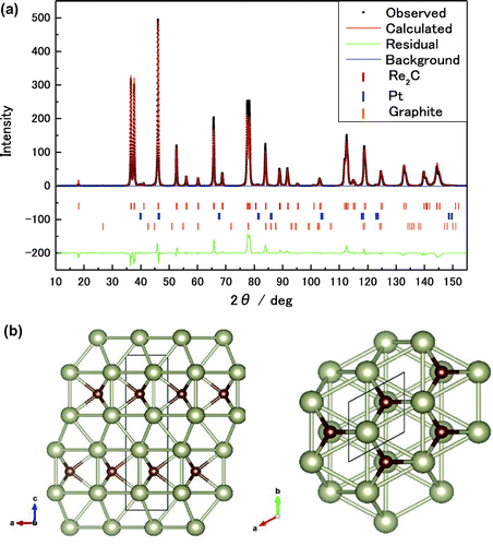
Note: Large silver dots are Re, and the small brown dots are C.
Figure 4. Rietveld refinements from XRD data with RIETAN-FP (Izumi & Momma, Citation2007). (a) Crystalline phases in simulation are Re2C, Pt, and graphite. (b) Crystal structure of Re2C parallel (left) or perpendicular (right) to c-axis.

Figure 5. High-pressure XRD patterns of increasing (a) and decreasing (b) pressure were recorded at PF, Tsukuba using DAC. Dependences of volume, and a- and c-axes on pressure are shown in panel (c).
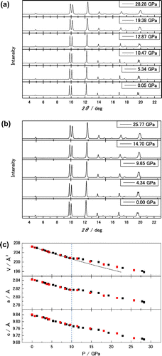
Notes: Black and red squares indicate experimental data for increasing and decreasing pressure, respectively. Compression data show kink at 10 GPa. Blue dotted vertical line at 10 GPa is guide for eye to show the beginning of this critical change. Solid line on volume compression data is fit line to third-order Birch–Murnaghan EOS.
Figure 5. High-pressure XRD patterns of increasing (a) and decreasing (b) pressure were recorded at PF, Tsukuba using DAC. Dependences of volume, and a- and c-axes on pressure are shown in panel (c).

Figure 6. Full width at half maximum (FWHM) of (0 0 6) and (1 1 0) diffraction lines of XRD spectra obtained from experiment at PF.
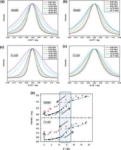
Notes: Figure (a–d) are measured profiles. Each profile is shifted to zero degree and overlapped for comparison. Black and red dots are FWHM for increasing and decreasing pressure (e), respectively.
Figure 6. Full width at half maximum (FWHM) of (0 0 6) and (1 1 0) diffraction lines of XRD spectra obtained from experiment at PF.