494
Views
0
CrossRef citations to date
0
Altmetric
Research Article

A functional renormalization group application to the scanning tunneling microscopy experiment

& | (Reviewing Editor)
Article: 1110940 | Received 10 Feb 2015, Accepted 18 Oct 2015, Published online: 08 Dec 2015

Figures & data

Figure 1. STM tip coupled to a host surface with an impurity. Notes: The tunneling matrix elements t12,t13 and t23 represent the couplings tip-impurity, tip-surface and impurity-surface, respectively. The tip-impurity lateral distance is denoted by r.
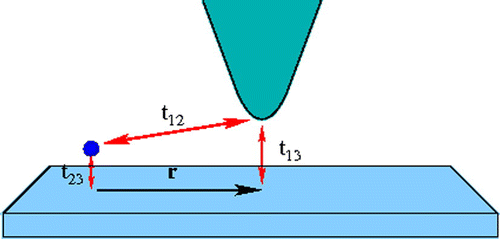
Figure 1. STM tip coupled to a host surface with an impurity. Notes: The tunneling matrix elements t12,t13 and t23 represent the couplings tip-impurity, tip-surface and impurity-surface, respectively. The tip-impurity lateral distance is denoted by r.

Figure 2. The Green functions of the impurity g(ω), substrate gk(ω), and tip gp(ω). Notes: Feynman diagrams for the hybridizations t23, t12 and t13. The self-energy Σtun include two tunneling events: an electron can tunnel from the impurity to the substrate and from the impurity to the tip. The interaction t~12 contains the physical event that an electron from the tip jump to the surface and then to the impurity.
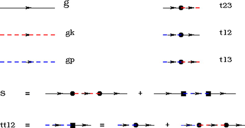
Figure 2. The Green functions of the impurity g(ω), substrate gk(ω), and tip gp(ω). Notes: Feynman diagrams for the hybridizations t23, t12 and t13. The self-energy Σtun include two tunneling events: an electron can tunnel from the impurity to the substrate and from the impurity to the tip. The interaction t~12 contains the physical event that an electron from the tip jump to the surface and then to the impurity.

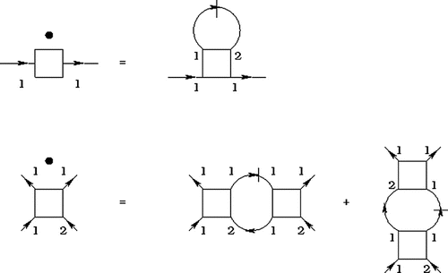
Figure 3. Flow equations. Notes: The dots over the vertices indicate a derivative with respect to the flow parameter Λ, the lines connecting different vertices are different Green’s functions in the Keldysh formalism. Each of the Green’s functions have a contribution from the self-energy in Figure which is denoted by a contribution Γ to the Green’s function.

Figure 3. Flow equations. Notes: The dots over the vertices indicate a derivative with respect to the flow parameter Λ, the lines connecting different vertices are different Green’s functions in the Keldysh formalism. Each of the Green’s functions have a contribution from the self-energy in Figure 2 which is denoted by a contribution Γ to the Green’s function.

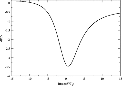
Figure 4. The differential conductance for r=0 in units of kF-1. A negative differential conductance develops over the whole range.

Figure 4. The differential conductance for r=0 in units of kF-1. A negative differential conductance develops over the whole range.

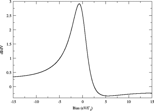
Figure 5. The differential conductance for r=2 in units of kF-1. A positive Lorentzian is developed when the STM tip is away from the impurity.

Figure 5. The differential conductance for r=2 in units of kF-1. A positive Lorentzian is developed when the STM tip is away from the impurity.