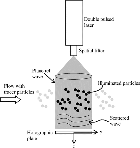
Figures & data
Figure 1. Basic experimental PIV set-up uses one camera while stereo-PIV set-up employs two cameras for the same flow measurement.
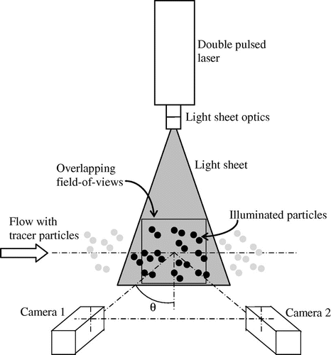
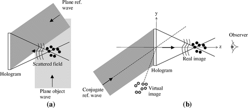
Figure 4. Off-axis viewing of an in-line hologram [after Meng and Hussain (Citation1991)].
![Figure 4. Off-axis viewing of an in-line hologram [after Meng and Hussain (Citation1991)].](/cms/asset/7555b913-fad3-430c-a2e4-2383ec24d7dd/oaph_a_1142819_f0004_b.gif)
Figure 5. Stereo-HPIV [after Scherer and Bernal (Citation1997)].
![Figure 5. Stereo-HPIV [after Scherer and Bernal (Citation1997)].](/cms/asset/deb541ff-9be2-4786-870c-ce995fa30f1d/oaph_a_1142819_f0005_b.gif)
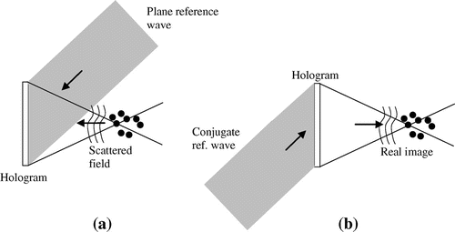
Figure 6. Forward-scatter off-axis holographic particle (a) recording and (b) reconstruction setups.
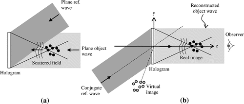
Figure 7. (a) High-pass filtering technique used in the holographic recording of forward-scatter off-axis geometry. (b) Holographic reconstruction eventually results in the suppression of the illumination beam [after Liu and Hussain (Citation1998)].
![Figure 7. (a) High-pass filtering technique used in the holographic recording of forward-scatter off-axis geometry. (b) Holographic reconstruction eventually results in the suppression of the illumination beam [after Liu and Hussain (Citation1998)].](/cms/asset/6404f4eb-6184-407c-8c69-d82bcf8f637b/oaph_a_1142819_f0007_b.gif)
Figure 8. Optical arrangement that utilized triangular tank with a mirror to simultaneously record an object and its mirror image [after Sheng et al. (Citation2003)].
![Figure 8. Optical arrangement that utilized triangular tank with a mirror to simultaneously record an object and its mirror image [after Sheng et al. (Citation2003)].](/cms/asset/7661ee07-dea3-41f3-851d-26202677e1ae/oaph_a_1142819_f0008_oc.gif)
Figure 9. Schematic diagram to suppress the DC effect [after Barnhart et al. (Citation1994)].
![Figure 9. Schematic diagram to suppress the DC effect [after Barnhart et al. (Citation1994)].](/cms/asset/1e549ceb-79ac-4cfb-9ea3-a31974d6c109/oaph_a_1142819_f0009_b.gif)
Figure 10. Holographic recording set-up utilizing light sheet object beam [after Fabry (Citation1998)].
![Figure 10. Holographic recording set-up utilizing light sheet object beam [after Fabry (Citation1998)].](/cms/asset/8c552efe-9c05-4022-aa93-da04bcedf236/oaph_a_1142819_f0010_b.gif)
Figure 11. Use of a prism in the reconstruction geometry to produce stereoscopic pairs of particle images [after Fabry (Citation1998)]. The 3D particle displacement, s is determined such that s = sqrt(si2 + s22).
![Figure 11. Use of a prism in the reconstruction geometry to produce stereoscopic pairs of particle images [after Fabry (Citation1998)]. The 3D particle displacement, s is determined such that s = sqrt(si2 + s22).](/cms/asset/83007408-94ed-4575-aca8-8e75abd6cfb6/oaph_a_1142819_f0011_b.gif)
Figure 12. Hologram recording with a tilted object beam to suppress zero-order diffraction [after Von Ellenrieder et al. (Citation2001)].
![Figure 12. Hologram recording with a tilted object beam to suppress zero-order diffraction [after Von Ellenrieder et al. (Citation2001)].](/cms/asset/8d960d75-6abd-4e04-bf71-c45198c07a7f/oaph_a_1142819_f0012_b.gif)
Figure 14. Employment of cylindrical light volume and alignment grid in side-scatter geometry. Planar HPIV setup employs a light sheet in place of the existing cylindrical light volume [after Lozano et al. (Citation1999)].
![Figure 14. Employment of cylindrical light volume and alignment grid in side-scatter geometry. Planar HPIV setup employs a light sheet in place of the existing cylindrical light volume [after Lozano et al. (Citation1999)].](/cms/asset/c3519662-8e50-4b98-977d-6ce08b6502ec/oaph_a_1142819_f0014_b.gif)
Figure 15. (a) Holographic recording and (b) reconstruction using light-in-flight holography technique [after Herrmann et al. (Citation1997)].
![Figure 15. (a) Holographic recording and (b) reconstruction using light-in-flight holography technique [after Herrmann et al. (Citation1997)].](/cms/asset/1057b4ac-ac01-468d-a04b-ddaaadea8e3e/oaph_a_1142819_f0015_b.gif)

