475
Views
8
CrossRef citations to date
0
Altmetric
Research Article

The multifunctional process of resonance scattering and generation of oscillations by nonlinear layered structures

& | (Reviewing Editor)
Article: 1158342 | Received 05 Dec 2015, Accepted 18 Feb 2016, Published online: 23 Mar 2016

Figures & data

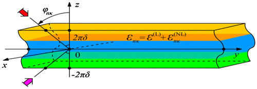
Figure 1. The nonlinear dielectric layered structure.

Figure 1. The nonlinear dielectric layered structure.

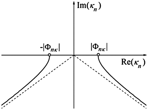
Figure 2. The geometry of the two-sheeted Riemann surfaces H.

Figure 2. The geometry of the two-sheeted Riemann surfaces Hnκ.

Figure 3. Relative portion of energy generated in the third harmonic W3κ/Wκ, the scattering Rκ+,Rκ- and generation R3κ+R3κ- coefficients for α = −0.01 (left top/bottom) and for α = +0.01 (right top/bottom).
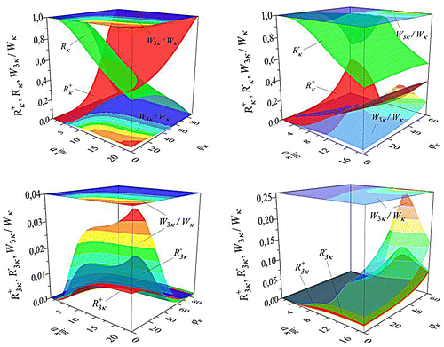
Figure 3. Relative portion of energy generated in the third harmonic W3κ/Wκ, the scattering Rκ+,Rκ- and generation R3κ+R3κ- coefficients for α = −0.01 (left top/bottom) and for α = +0.01 (right top/bottom).

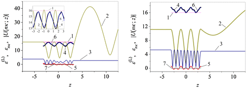
Figure 4. Curves at aκinc=24, ϕκ = 0° for α = −0.01 (left) and at aκinc=14, ϕκ = 66° for α = +0.01 (right): 1 – εL, 2 – Uκ;z, 3 – U3κ;z, 4 – Reεκ, 5 – Imεκ, 6 – Reε3κ, 7 – Imε3κ0.

Figure 4. Curves at aκinc=24, ϕκ = 0° for α = −0.01 (left) and at aκinc=14, ϕκ = 66° for α = +0.01 (right): 1 – εL, 2 – Uκ;z, 3 – U3κ;z, 4 – Reεκ, 5 – Imεκ, 6 – Reε3κ, 7 – Imε3κ≡0.

Figure 5. Scattered Uκaκinc,z and generated U3κaκinc,z fields in the nonlinear layer at ϕκ = 0° for α = −0.01 (left) and ϕκ = 60° for α = +0.01 (right).
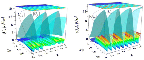
Figure 5. Scattered Uκaκinc,z and generated U3κaκinc,z fields in the nonlinear layer at ϕκ = 0° for α = −0.01 (left) and ϕκ = 60° for α = +0.01 (right).

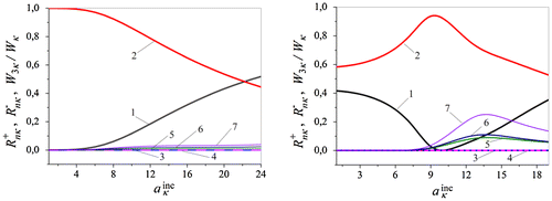
Figure 6. Curves at ϕκ = 0°, for α = −0.01 (left) and at ϕκ = 60° for α = +0.01 (right): 1 – Rκ+, 2 – Rκ-, 3 – R2κ+0, 4 – R2κ-0, 5 – R3κ+, 6 – R3κ-, 7 – W3κ/Wκ.

Figure 6. Curves at ϕκ = 0°, for α = −0.01 (left) and at ϕκ = 60° for α = +0.01 (right): 1 – Rκ+, 2 – Rκ-, 3 – R2κ+≡0, 4 – R2κ-≡0, 5 – R3κ+, 6 – R3κ-, 7 – W3κ/Wκ.

Figure 7. Curves at ϕκ = 0° (left) and ϕκ = 60° (right): 1 … κ=κinc=0.375, 2 … 3κ=κgen=3κinc; 3.1 … Reκ1L, 3.2 … Imκ1L, 4.1 … Reκ3L, 4.2 … Imκ3L for α ≡ 0; 5.1 … Reκ1NL, 5.2 … Imκ1NL, 6.1 … Reκ3NL, 6.2 … Imκ3NL for α = −0.01 (left) and for α = +0.01 (right).

Figure 7. Curves at ϕκ = 0° (left) and ϕκ = 60° (right): 1 … κ=κinc=0.375, 2 … 3κ=κgen=3κinc; 3.1 … Reκ1L, 3.2 … Imκ1L, 4.1 … Reκ3L, 4.2 … Imκ3L for α ≡ 0; 5.1 … Reκ1NL, 5.2 … Imκ1NL, 6.1 … Reκ3NL, 6.2 … Imκ3NL for α = −0.01 (left) and for α = +0.01 (right).

Figure 8. The Q-factor and the relative Q-factor. Curves: 1 … Qκ1, 3 … Qκ3, and … Qκ1/Qκ3 at κinc=0.375, κn=κnNL, n=1,3, for ϕκ = 0°, α = −0.01 (left top/bottom) and for ϕκ = 60°, α = +0.01 (right top/bottom).
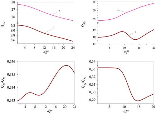
Figure 8. The Q-factor and the relative Q-factor. Curves: 1 … Qκ1, 3 … Qκ3, and … Qκ1/Qκ3 at κinc=0.375, κn=κnNL, n=1,3, for ϕκ = 0°, α = −0.01 (left top/bottom) and for ϕκ = 60°, α = +0.01 (right top/bottom).

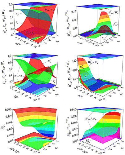
Figure 9. The properties of the nonlinear structure at incidence angles ϕκ,180-ϕκ with ϕκ0,90 for amplitudes aκinc,bκinc: (top left/right) aκinc0, bκinc=0; (middle left/right) aκinc=38, bκinc0; (bottom left/right) aκinc=bκinc here Rnκ+=Rnκ-, n=1,3.

Figure 9. The properties of the nonlinear structure at incidence angles ϕκ,180∘-ϕκ with ϕκ∈0∘,90∘ for amplitudes aκinc,bκinc: (top left/right) aκinc≠0, bκinc=0; (middle left/right) aκinc=38, bκinc≠0; (bottom left/right) aκinc=bκinc here Rnκ+=Rnκ-, n=1,3.

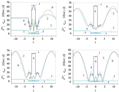
Figure 10. Curves: 0 – Uκ;z for αz0, 1 – εL, 2 – Uκ;z, 3 – U3κ;z, 4 – Reεκ, 5 – Imεκ, 6 – Reε3κ, 7 – Imε3κ0, at ϕκ,180-ϕκ with ϕκ = 0° and (top left): aκinc=38,bκinc=0; (top right): aκinc=38,bκinc=20; (bottom left): aκinc=38,bκinc=30; (bottom right) aκinc,bκinc with aκinc=bκinc=38.

Figure 10. Curves: 0 – Uκ;z for αz≡0, 1 – εL, 2 – Uκ;z, 3 – U3κ;z, 4 – Reεκ, 5 – Imεκ, 6 – Reε3κ, 7 – Imε3κ≡0, at ϕκ,180∘-ϕκ with ϕκ = 0° and (top left): aκinc=38,bκinc=0; (top right): aκinc=38,bκinc=20; (bottom left): aκinc=38,bκinc=30; (bottom right) aκinc,bκinc with aκinc=bκinc=38.