Figures & data
Figure 1. Diagram of OMC marker and EM receiver layout during rowing trials. Top-down view of sensors affixed to the instrumented ergometer (left). Anterior and posterior views of sensors as applied to subject anatomical landmarks (right). Relative position of key stroke occurrences (catch, mid-slide, release) is indicated to the left of the slide rail
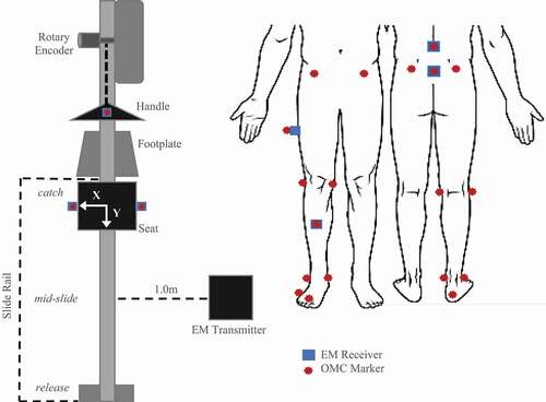
Figure 2. Difference from ground truth position of static marker/receivers in A/P plane for OMC and EM systems. Similar patterns were found for M/L and S/I directions
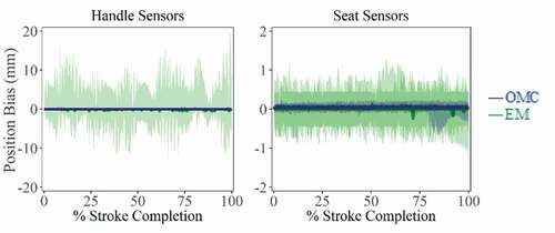
Figure 3. A/P plane displacements (mean ± 95% CI) for OMC and EM systems across all stroke rates. (a) Before phase-lag correction, EM system capture latency is visible as a rightward shift in mean displacement for handle and seat trajectories. (b) After phase-lag correction using least-squares fitting, differences between systems decreased, as indicated by smaller RMSE values
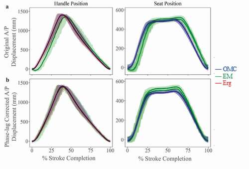
Figure 4. Seat width (mean ± SD), calculated as the M/L distance between markers/receivers fixed to left and right sides of ergometer seat. The OMC system slightly overestimates seat width throughout the stroke while the EM system was less consistent, underestimating seat width near the catch and release positions and overestimating seat width during mid-slide. Catch occurs at 0% and 100%. Release occurs at ~40%
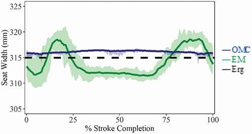
Table 1. Geers metric for agreement between tracking systems as a function of magnitude and phase differences. Values of <0.3 are good (green), between 0.3 and 0.5 moderate (yellow), and >0.5 has poor agreement (red). Values for directly tracked markers/receivers and calculated joint centers, before and after phase-lag correction, are shown. Deviations attributed to phase were reduced by applying phase-lag correction. Negative metric values indicate an under-prediction of EM displacements relative to OMC. Analytical formulations of Geers metric may be found in Schwer (Citation2007)
Figure 5. Co-localized marker tracking (mean ± 95% CI) in three dimensions with and without phase correction. These show similar trends despite EM capture latency, with each mean trajectory falling within well overlapped 95% confidence intervals. Agreement between systems in A/P displacements shows the most improvement with phase-lag correction. M/L and S/I displacements show more apparent magnitude differences between systems, but without a clear trend in over/under estimation of one system relative the other
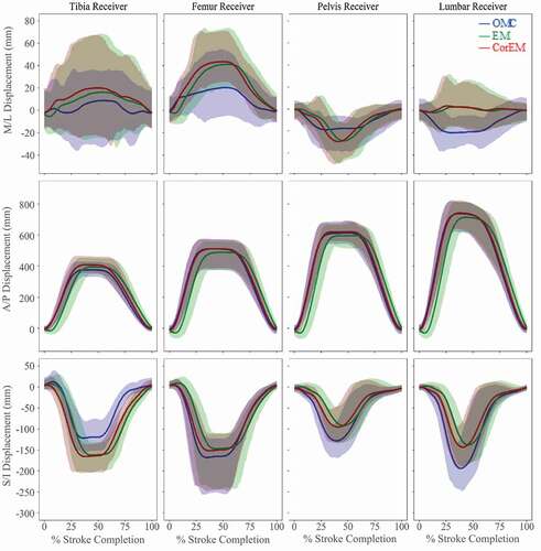
Figure 6. Simultaneous joint center tracking using the three methods (mean ± 95% CI). A/P and S/I displacements show improved trajectory agreement with phase-lag correction. S/I hip joint movement and A/P ankle joint movement show confidence intervals, which do not substantially overlap, with both having large magnitude discrepancies. Confidence of agreement in M/L displacements is ambiguous due to larger relative standard deviations, particularly at knee joint center
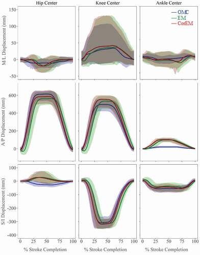
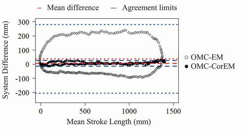
Figure 7. Bland-Altman comparison of bias and limits of agreement (mean ± 95% CI) during dynamic apparatus tracking for A/P handle displacements between OMC and EM systems before (OMC-EM) and after (OMC-CorEM) phase-lag correction. After phase-lag correction the cyclic trend collapses and the limits of agreement contract