Figures & data
Figure 1. An experimental abutment die for crown restorations made of zirconium oxide (a). An experimental crown restoration adhered on the abutment die. A dotted line describes the non-anatomic flat surface that is created at the incisor edge of a crown restoration (b). A commercially available dental ceramic block for a CAD/CAM (upper) and an experimental all-FRC block for CAD/CAM (lower) (c). Aluminum foils were placed between the incisor edge of the crown restoration and the load cell during the fracture test (d). Abbreviations: CAD/CAM: computer-aided design and manufacturing; FRC: fiber-reinforced composite.
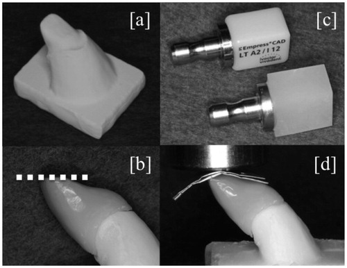
Table 1. Materials used in the study.
Figure 2. The mean values for the fracture load (N) (bars) and toughness (Ncm) (line) of the crown restorations. The vertical lines represent the standard deviations. The stars above the columns indicate that there is no significant difference between the eMx group and the a-FRC group for fracture load. Abbreviations: FRC: fiber-reinforced composite.
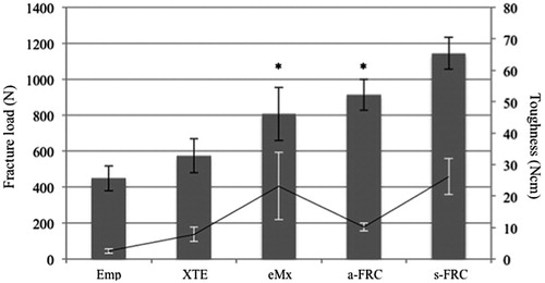
Figure 3. The graph shows typical load-strain curves of all tested crown restorations.
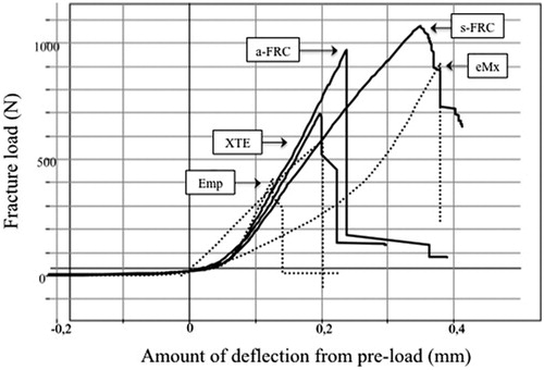
Figure 4. The typical fracture appearance of restorations made from brittle materials (Emp, XTE and eMx groups) (a) and restorations made from single-structure FRCs (a-FRC and s-FRC groups) (b). For the restorations made from the brittle materials, catastrophic failures were observed in which an initial crack initiated the fracture with a single fracture line (a). For restorations made from single-structure FRCs, local crushing failures were observed (b). The restorations made from FRCs maintained their original shapes until fracture, although multiple fracture cracks occurred in the incisor edge of the restorations. Abbreviation: FRC: fiber-reinforced composite.
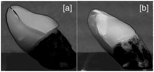
Figure 5. Scanning electron micro-morphologies show the prosthetic surfaces of crown restorations made from single-structure FRCs. The surfaces of a-FRC with magnifications of ×100 and of ×500 are shown in (a) and (b), whereas those of s-FRC with magnifications of ×100 and ×500 are presented in (c) and (d), respectively. Sections of chopped fiberglass were observed on the surface of a-FRC as indicated by arrows in (b), whereas parallel oriented fibers were present on the surface of s-FRC as indicated by arrows in (d). For the surface of s-FRC, the crushed edges of the fiberglass and the lateral side of the oriented fiberglass are indicated by horizontal arrows and vertical arrows, respectively, in (d). Abbreviation: FRC: fiber-reinforced composite.
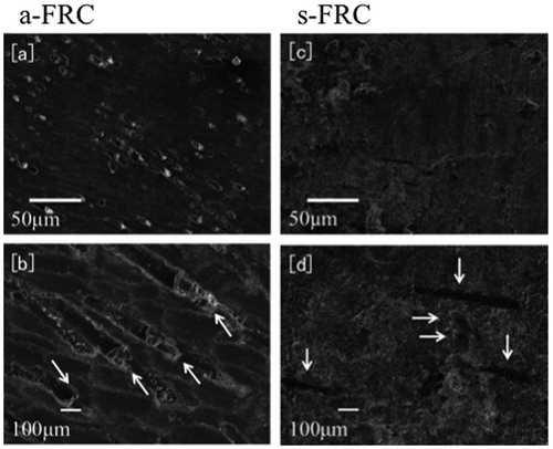
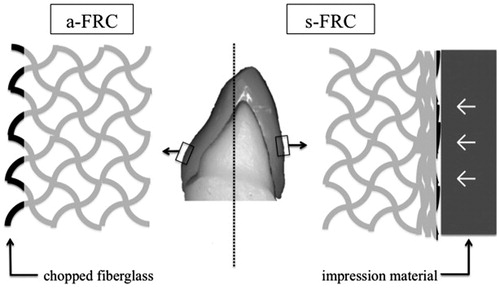
Figure 6. A schematic drawing of the distinct distributions of fiberglass (black lines) on the prosthetic surfaces of single-structure FRC restorations. The fiberglass in a-FRC was chopped during the milling of CAD/CAM (left), while the fiberglass in s-FRC was crushed by the impression material during the preparation (right). Abbreviations: CAD/CAM: computer-aided design and manufacturing; FRC: fiber-reinforced composite.