
Figures & data
Table 1. Groups listed with abbreviation and surface treatment procedure.
Figure 1. Schematic view of etching process. Diffusion of active etching agents in the melt and to the solid zirconia surface with simultaneous diffusion of etching products, fluorozirconates, from the zirconia surface and into the melt.
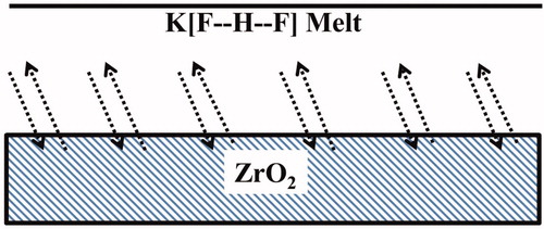
Figure 2. Schematic illustration of combination of materials (zirconia bonded to zirconia ceramic).
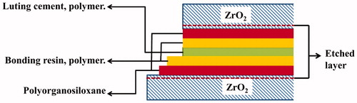
Table 2. Mean shear bond strength values of all groups tested along with the standard deviation.
Figure 3. SEM images of the zirconia disc specimens (reference) after different surface treatments (a) Sandblasted; (b) K[FHF] powder, etched; (c) K[FHF] slurry, etched; (d) NH4[FHF] powder etched; (e) NH4[FHF] slurry etched.
![Figure 3. SEM images of the zirconia disc specimens (reference) after different surface treatments (a) Sandblasted; (b) K[FHF] powder, etched; (c) K[FHF] slurry, etched; (d) NH4[FHF] powder etched; (e) NH4[FHF] slurry etched.](/cms/asset/f132f84c-ccc2-47c7-83fd-31dc6542e9bb/iabo_a_1309658_f0003_b.jpg)
Figure 4. SEM images of the zirconia disc specimens after shear bond measurements (a) EKPS (b) EKPU and (c) EKSU.
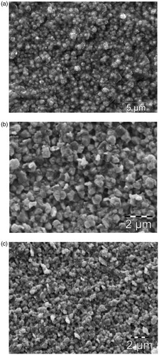
Figure 5. SEM images of the fracture surfaces of zirconia disc and rod specimens after shear bond testing measurements. Light areas are thin layers and darker areas are thicker layers of bonding resin cement. (a) SBS zirconia disc, contact area at the upper part; (b) SBS zirconia rod, contact area at the upper part; (c) EASS zirconia disc, contact area; (d) EASS zirconia rod, contact area.
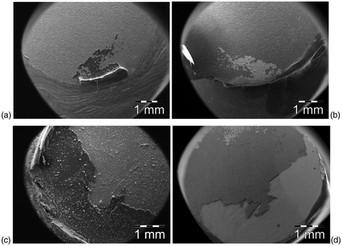
Figure 6. Rietveld fit to XRD data for Y-TZP specimens after different surface treatments. (a) Polished; (b) Sandblasted; (c) K[FHF] slurry etched; (d) NH4[FHF] slurry etched. Upper plots showing observed and calculated intensities, lower plot shows the difference for the samples. *Monoclinic peak.
![Figure 6. Rietveld fit to XRD data for Y-TZP specimens after different surface treatments. (a) Polished; (b) Sandblasted; (c) K[FHF] slurry etched; (d) NH4[FHF] slurry etched. Upper plots showing observed and calculated intensities, lower plot shows the difference for the samples. *Monoclinic peak.](/cms/asset/6bf4befc-474e-463c-bdcf-d67dfca2deb0/iabo_a_1309658_f0006_c.jpg)
Table 3. Results of quantitative and crystallite size analysis by the Rietveld method.
Figure 7. FT-IR spectra of (a) etched surface product and (b) K2[ZrF6] in the region 510–460 cm−1. The figures on the absorption peaks represent wavenumbers and peak areas.
![Figure 7. FT-IR spectra of (a) etched surface product and (b) K2[ZrF6] in the region 510–460 cm−1. The figures on the absorption peaks represent wavenumbers and peak areas.](/cms/asset/f3b9b09d-a659-4551-860e-d8b7077b0c42/iabo_a_1309658_f0007_b.jpg)
Figure 8. FT-IR spectra for (a) etched surface product and (b) K2[ZrF6] in the region 500–200 cm−1.
![Figure 8. FT-IR spectra for (a) etched surface product and (b) K2[ZrF6] in the region 500–200 cm−1.](/cms/asset/9e0f1bfe-cca8-492c-bcb0-c629131248db/iabo_a_1309658_f0008_b.jpg)