Figures & data
Fig. 1. Typical CFD computational domain.
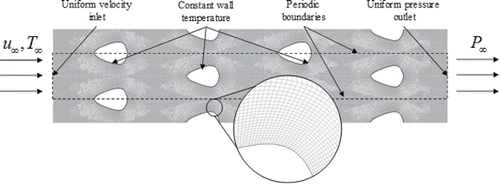
Fig. 2. Air thermos-physical properties as function of temperature and relative humidity.
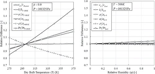
Fig. 3. Tube shape parameterization.
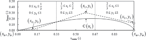
Fig. 4. First order analyses I: compactness, material utilization and internal volume.
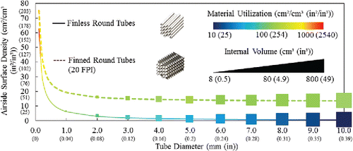
Fig. 5. First order analyses II: fin-to-tube surface ratio.
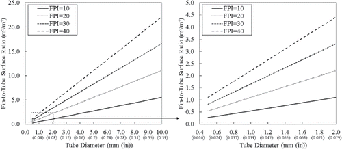
Fig. 6. Second order analysis: thermal-hydraulic characteristics of finless and finned surfaces.
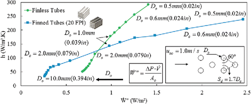
Fig. 7. Tube shapes: a. Round; b. Ellipse; c. Eye; d. Airfoil leading edge; e. Airfoil trailing edge.
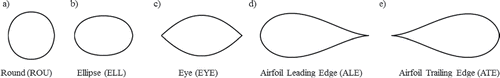
Fig. 8. Local thermal-hydraulic characteristics for round tube at constant Reynolds: a. hydraulic boundary layer; b. temperature gradient at the wall; c. tangential velocity gradient at the wall.
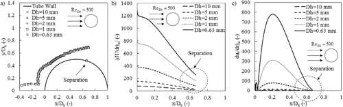
Fig. 9. Local thermal-hydraulic characteristics for round tube at constant velocity: a. hydraulic boundary layer; b. temperature gradient at the wall; c. tangential velocity gradient at the wall.
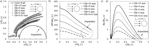
Fig. 10. Thermal-hydraulic performance of different tube shapes with same hydraulic diameter.
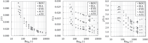
Fig. 11. Design problem: a. Generic finless HX; b. Baseline MCHX.
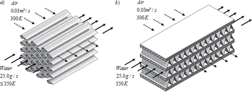
Fig. 12. CFD results for the NTHX-001: a. velocity; b. pressure; c. temperature.
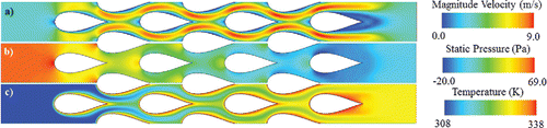
Fig. 13. Proof-of-concept NTHX-001.
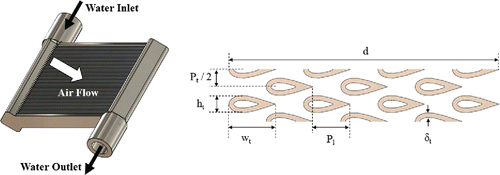
Table 1. NTHX-001 Numerical results compared to the baseline MCHX.
Fig. 14. Numerical optimization framework.
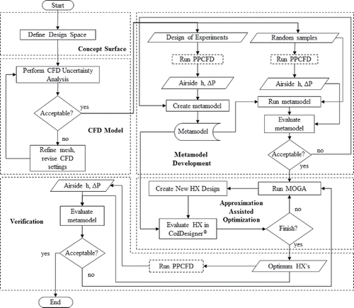
Fig. 15. Parallel parameterized CFD framework.
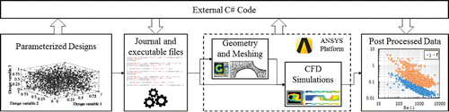
Table 2. Design space.
Fig. 16. Scaling, topology and shape variables.
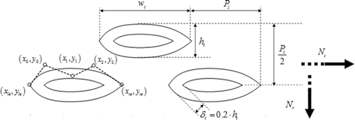
Fig. 17. GCI Analysis.
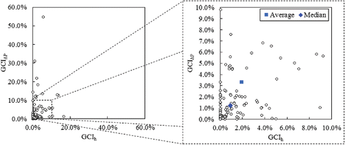
Fig. 18. Metamodel verification against 961 random samples.
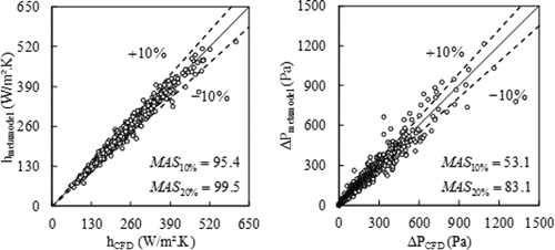
Fig. 19. Optimization results.
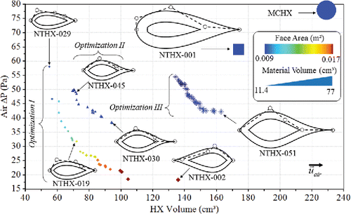
Fig. 20. Metamodel verification for the optimum designs.
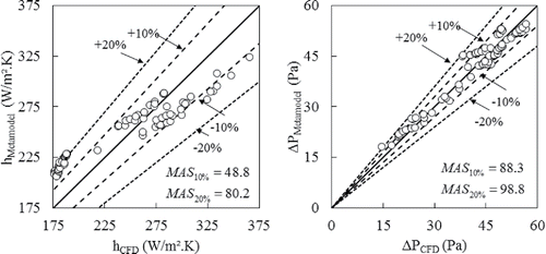
Fig. 21. Prototype NTHX-001 and blockage test images.
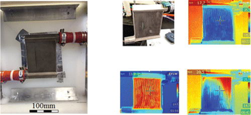
Fig. 22. Wind tunnel facility.
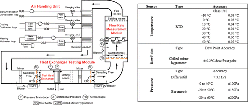
Fig. 23. Experimental energy balance and capacity validation.
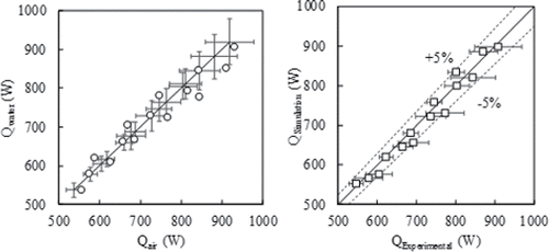
Fig. 24. NTHX-001 Airside thermal-hydraulic performance validation.
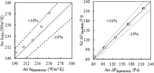
Fig. 25. CFD results for the NTHX-030 design: a. magnitude velocity; b. velocity angle; c. turbulence intensity.
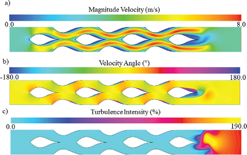
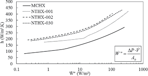
Fig. 26. Thermal-hydraulic performance of novel HX's for a wide range of Reynolds numbers.