3,163
Views
1
CrossRef citations to date
0
Altmetric
Original Articles

Field measurement and modeling of UVC cooling coil irradiation for heating, ventilating, and air conditioning energy use reduction (RP-1738)—Part 1: Field measurements

, &
Pages 588-599 | Received 03 Jan 2017, Accepted 19 Oct 2017, Published online: 11 Dec 2017

Figures & data

Table 1. Site and HVAC system characteristics.

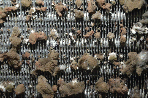
Fig. 1. Image of fouling at Tampa site, downstream side of coil. Visible fouling is fungal growth.

Fig. 1. Image of fouling at Tampa site, downstream side of coil. Visible fouling is fungal growth.

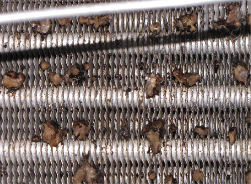
Fig. 2. Close-up of fouling at PSU site, upstream side of coil. Note the accumulation of fouling at the space between the tubes.
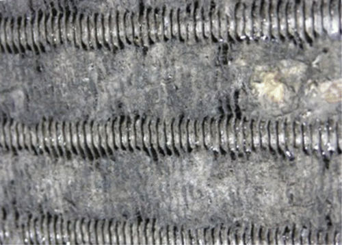
Fig. 2. Close-up of fouling at PSU site, upstream side of coil. Note the accumulation of fouling at the space between the tubes.

Table 2. Field site UV lamp information.

Table 3. Measurement instrumentation.

Fig. 3. Instrumentation schematic (T = temperature, RH = relative humidity, DP = pressure differential, CHW = chilled water piping).
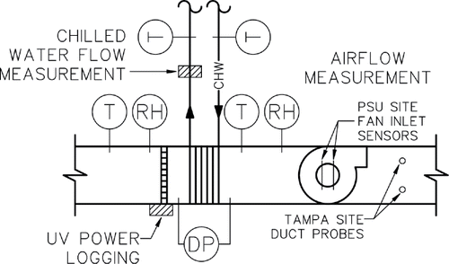
Fig. 3. Instrumentation schematic (T = temperature, RH = relative humidity, DP = pressure differential, CHW = chilled water piping).

Fig. 4. Use of coil model in typical and inverse applications.

Fig. 4. Use of coil model in typical and inverse applications.

Table 4. UA model use of input variables in simulation software.

Table 5. Conditions for design UA value calculation.

Fig. 5. Tampa site coil before application of UVGI.

Fig. 5. Tampa site coil before application of UVGI.

Fig. 6. Tampa site coil after 13 months of UVGI exposure.

Fig. 6. Tampa site coil after 13 months of UVGI exposure.

Table 6. Binning range and interval for analysis of Tampa ΔP data.

Fig. 7. Tampa mean airside pressure drop versus time for example bins; a. 3800–4000 cfm and 44.4–47.8 kBTU/h (1.79–1.89 m3/s and 13–14 kW latent load); b. 4000–4200 cfm and 51.2–54.6 kBTU/h (1.89–1.98 m3/s and 15–16 kW). Error bars are ±2% of full scale for illustration, as the calculated standard deviations using the point measurement error of 0.14% full scale were too small to be visible.
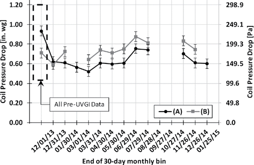
Fig. 7. Tampa mean airside pressure drop versus time for example bins; a. 3800–4000 cfm and 44.4–47.8 kBTU/h (1.79–1.89 m3/s and 13–14 kW latent load); b. 4000–4200 cfm and 51.2–54.6 kBTU/h (1.89–1.98 m3/s and 15–16 kW). Error bars are ±2% of full scale for illustration, as the calculated standard deviations using the point measurement error of 0.14% full scale were too small to be visible.
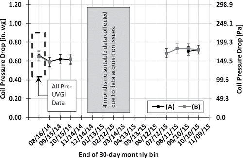
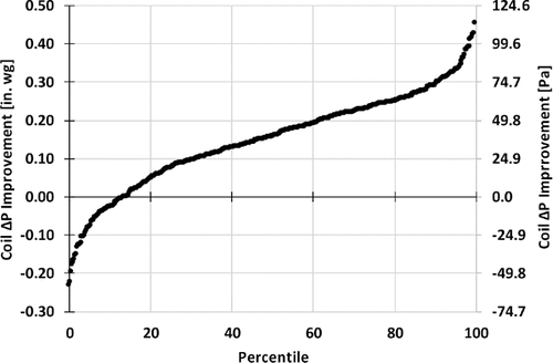
Fig. 8. Tampa mean pressure drop improvement across all months and all bins.

Fig. 8. Tampa mean pressure drop improvement across all months and all bins.

Table 7. Binning range and interval for analysis of PSU ΔP data.

Fig. 9. PSU mean air side pressure drop versus time for example bins; a. 14,200–14,400 cfm and 57.9–68.2 kBTU/h (6.61–6.70 m3/s and 17.5–20.0 kW); b. 14,200–14,400 cfm and 68.2–76.8 kBTU/h (6.61–6.70 m3/s and 20.0–22.5 kW). Error bars are ±2% of full scale for illustration, as the calculated standard deviations using the point measurement error of 0.14% full scale were too small to be visible.
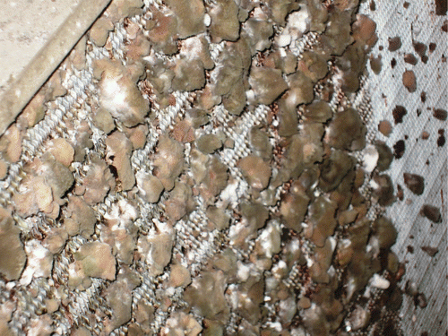
Fig. 9. PSU mean air side pressure drop versus time for example bins; a. 14,200–14,400 cfm and 57.9–68.2 kBTU/h (6.61–6.70 m3/s and 17.5–20.0 kW); b. 14,200–14,400 cfm and 68.2–76.8 kBTU/h (6.61–6.70 m3/s and 20.0–22.5 kW). Error bars are ±2% of full scale for illustration, as the calculated standard deviations using the point measurement error of 0.14% full scale were too small to be visible.
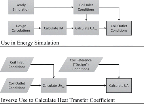
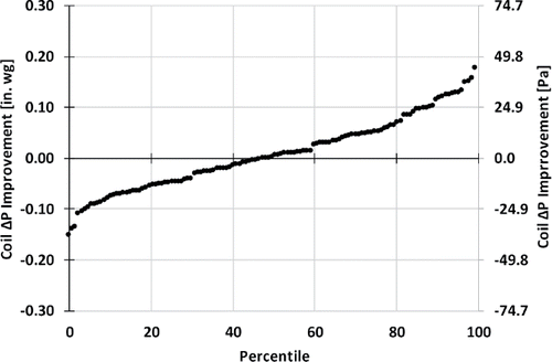
Fig. 10. PSU mean pressure drop improvement across all months and all bins.

Fig. 10. PSU mean pressure drop improvement across all months and all bins.

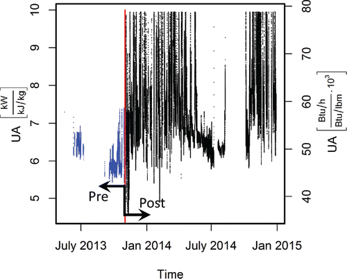
Fig. 11. Tampa UA versus time. Red line denotes when UV is turned on.

Fig. 11. Tampa UA versus time. Red line denotes when UV is turned on.

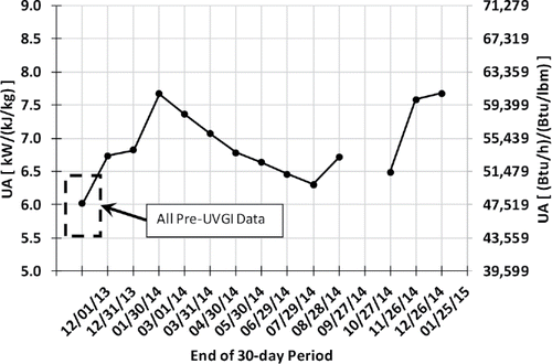
Fig. 12. Tampa UA vs. time, 0.60–0.65 SHR. Error bars are included, but are not visible.

Fig. 12. Tampa UA vs. time, 0.60–0.65 SHR. Error bars are included, but are not visible.

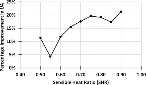
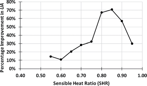
Fig. 13. Tampa percentage improvement in UA versus SHR. Horizontal axis values represent the upper limit of a 0.05-width bin.

Fig. 13. Tampa percentage improvement in UA versus SHR. Horizontal axis values represent the upper limit of a 0.05-width bin.

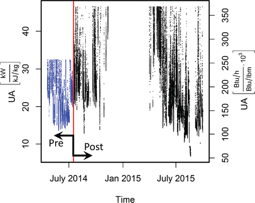
Fig. 14. PSU UA versus time. Red line denotes when UV is turned on.

Fig. 14. PSU UA versus time. Red line denotes when UV is turned on.

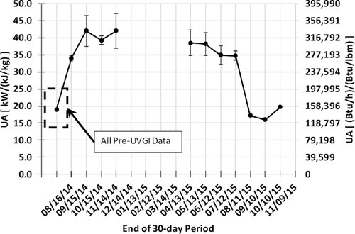
Fig. 15. PSU UA versus time, 0.80–0.85 SHR.

Fig. 15. PSU UA versus time, 0.80–0.85 SHR.

Fig. 16. PSU percentage improvement in UA versus SHR. Horizontal axis values represent the upper limit of a 0.05-width bin.

Fig. 16. PSU percentage improvement in UA versus SHR. Horizontal axis values represent the upper limit of a 0.05-width bin.