Figures & data
Fig. 1 Room air temperature control in cooling mode (VAV).
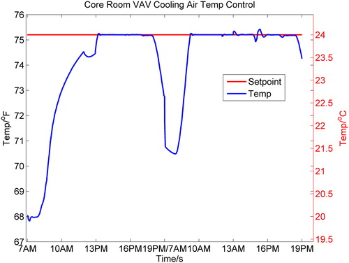
Fig. 2 Room supply airflow fraction in cooling mode (VAV).
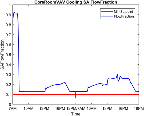
Fig. 3 Room air temperature control loop assessment (VAV cooling mode).
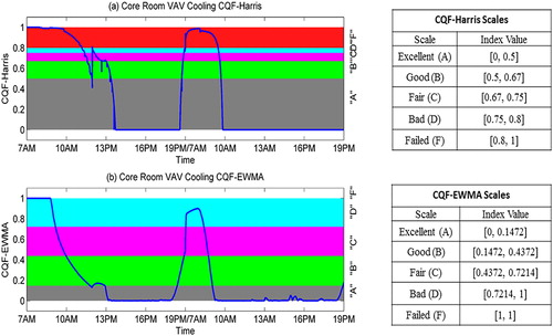
Fig. 4 Weighted control performance for room air temperature control (CQF-Harris).
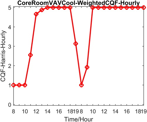
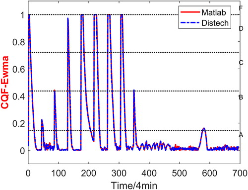
Fig. 5 Weighted control performance for room air temperature control (CQF-EWMA).
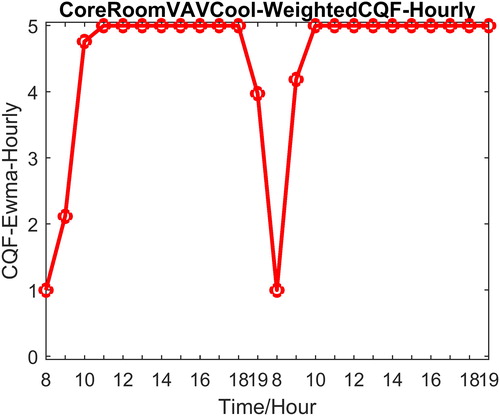
Table 1. Weighted CQF scores.
Fig. 6 Heat exchanger hot water supply temperature control.
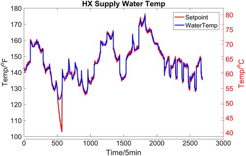
Fig. 7 Heat exchanger supply water valve opening.
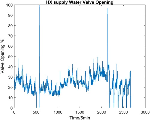
Fig. 8 CQF assessment for heat exchanger water supply temperature control loop: (left) CQF-Harris; (right) CQF-EWMA.
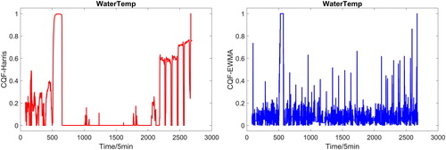
Fig. 9 AHU supply air static pressure control.
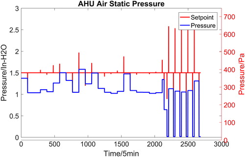
Fig. 10 AHU supply air fan speed.
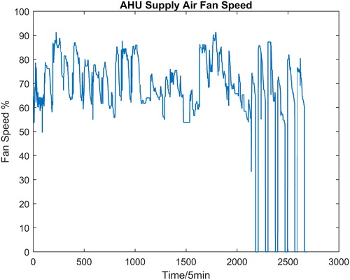
Fig. 11 Assessment for AHU supply air static pressure control: (left) CQF-Harris; (right) CQF-EWMA.
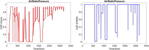
Fig. 12 Energy Resource Station—southeast view.
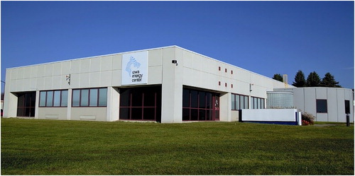
Fig. 13 Energy Resource Station floor plan.
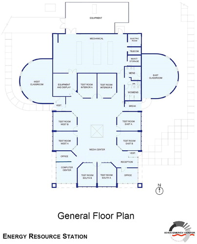
Fig. 14 Schematic of test room HVAC system.
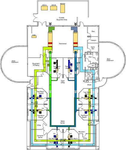
Table 2. ERS VAV box design specification.
Table 3. Stages of baseboard heat.
Table 4. Occupancy simulator control modes.
Table 5 Test design parameters.a
Fig. 15 CQF inputs and CQF-Harris (room cooling South B).
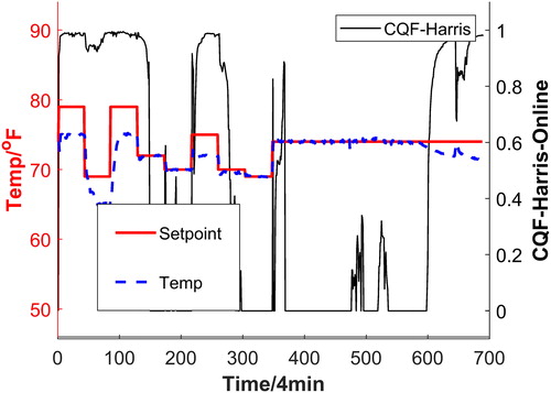
Fig. 16 CQF inputs and CQF-EWMA (room cooling South B).
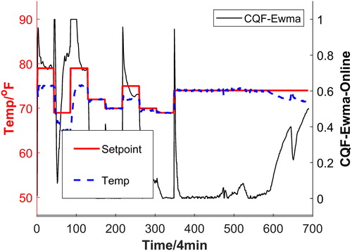
Fig. 17 CQF-Harris comparison (room cooling South B).
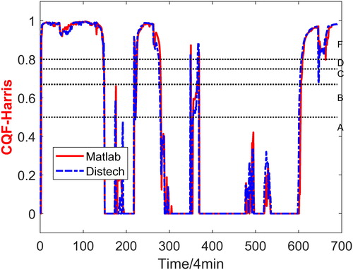
Fig. 18 CQF-EWMA comparison (room cooling South B).
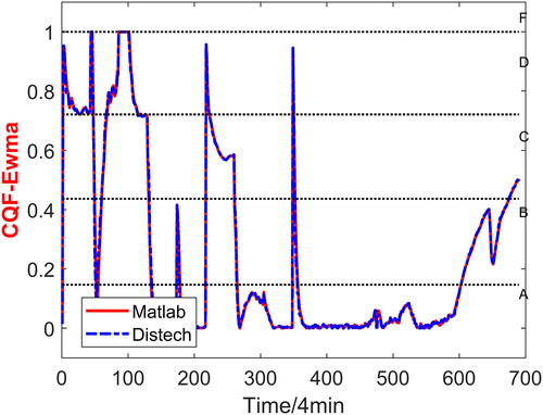
Fig. 19 CQF inputs and CQF-Harris (room heating West B).
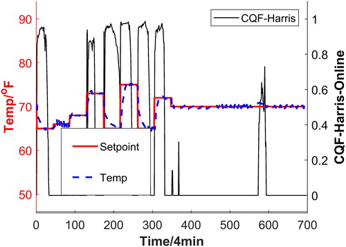
Fig. 20 CQF inputs and CQF-EWMA (room heating West B).
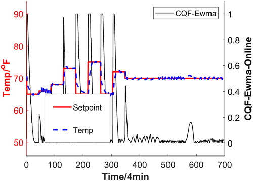
Fig. 21 CQF-Harris comparison (room heating West B).
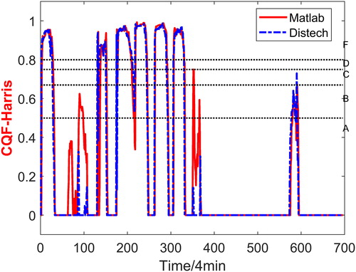
Fig. 22 CQF-EWMA comparison (room heating West B).