Figures & data

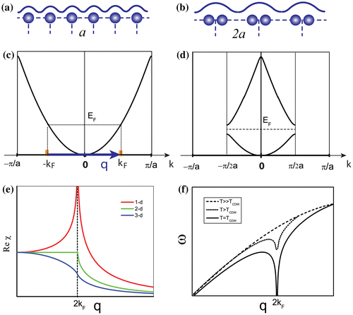
Figure 1. Illustration of the Peirls picture. (a) Atomic model of a 1D chain with lattice constant a above Tc. (b) Atomic model of the 1D chain with lattice constant changing to 2a below Tc. (c) Free electron band of the 1D chain above Tc. (d) Free electron band of the 1D chain below Tc with a gap opening at kF. (e) Plots of the real part of Linhard function for 1D, 2D and 3D free electron gas models. (f) Phonon energy of 1D atomic chain at different temperature.

Table 1. Comparison of the key features of typical CDW materials with Peierls’ model.
Figure 2. Illustration of the CDW state of TTF-TCNQ. (a) STM image at 63 K showing the normal state. (b) STM image at 36 K showing the CDW state. Reprinted with permission from Ref. [Citation26]. Copyright (2003) by the American Physical Society. (c) ARPES intensity mapping at EF of TTF-TCNQ at 60 K, showing a clear 1D FSN. Reprinted with permission from Ref. [Citation27]. Copyright (2013) by the Physical Society of Japan. (d) Resistivity vs. temperature measurements showing a clear metal–insulator transition at 55 K [Citation22]. (e) Inelastic neutron scattering results of the acoustic phonon dispersion showing a strong Kohn anomaly [Citation25].
![Figure 2. Illustration of the CDW state of TTF-TCNQ. (a) STM image at 63 K showing the normal state. (b) STM image at 36 K showing the CDW state. Reprinted with permission from Ref. [Citation26]. Copyright (2003) by the American Physical Society. (c) ARPES intensity mapping at EF of TTF-TCNQ at 60 K, showing a clear 1D FSN. Reprinted with permission from Ref. [Citation27]. Copyright (2013) by the Physical Society of Japan. (d) Resistivity vs. temperature measurements showing a clear metal–insulator transition at 55 K [Citation22]. (e) Inelastic neutron scattering results of the acoustic phonon dispersion showing a strong Kohn anomaly [Citation25].](/cms/asset/1db3a3fc-126e-49a6-98fb-5503976e0603/tapx_a_1343098_f0002_oc.gif)
Figure 3. Origin of the CDW in NbSe2. (a) Fermi Surface Contours [Citation10] with the experimental [Citation16,17] shown. (b) Reχ(q) and (c) Imχ(q) calculated from experimental data [Citation10] along the ΓM direction. (d) Extracted EPC matrix element
[Citation32]. (e) Measured phonon dispersion (points) at T = 8 K [Citation20] and calculated soft phonon behaviour (solid line) using
and an approximation for the bare phonon (dashed line) dispersion [Citation32].
![Figure 3. Origin of the CDW in NbSe2. (a) Fermi Surface Contours [Citation10] with the experimental [Citation16,17] shown. (b) Reχ(q) and (c) Imχ(q) calculated from experimental data [Citation10] along the ΓM direction. (d) Extracted EPC matrix element [Citation32]. (e) Measured phonon dispersion (points) at T = 8 K [Citation20] and calculated soft phonon behaviour (solid line) using and an approximation for the bare phonon (dashed line) dispersion [Citation32].](/cms/asset/0dfb43a8-bb70-4c31-a93a-9bc37e08feb4/tapx_a_1343098_f0003_oc.gif)
Figure 4. EPC associated with apical oxygen A1g phonon mode in optimally doped Bi2Sr2CaCu2O8+δ [Citation32]. (a) Fit to the measured phonon dispersion [Citation83] as a function of momentum. (b) Fit to the measured linewidth as a function of momentum. (c) extracted from the phonon [Citation83] and ARPES [Citation82] data.
![Figure 4. EPC associated with apical oxygen A1g phonon mode in optimally doped Bi2Sr2CaCu2O8+δ [Citation32]. (a) Fit to the measured phonon dispersion [Citation83] as a function of momentum. (b) Fit to the measured linewidth as a function of momentum. (c) extracted from the phonon [Citation83] and ARPES [Citation82] data.](/cms/asset/f17537b2-baec-4567-a5fb-bebdd5cccc54/tapx_a_1343098_f0004_oc.gif)
Figure 5. Resistivity vs. temperature measurements for typical CDW materials. (a) 1D chain TTF-TCNQ [Citation22]. (b) 1D chain NbSe3 [Citation85]. (c) 2D layered NbSe2 [Citation34].
![Figure 5. Resistivity vs. temperature measurements for typical CDW materials. (a) 1D chain TTF-TCNQ [Citation22]. (b) 1D chain NbSe3 [Citation85]. (c) 2D layered NbSe2 [Citation34].](/cms/asset/834c0b08-3c5f-42ee-8978-6730aac4b46c/tapx_a_1343098_f0005_oc.gif)
