Figures & data
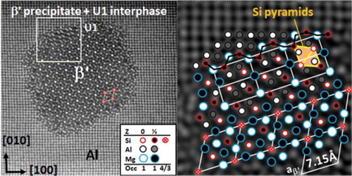
Figure 1. Al-side of the Al-Cu phase diagram [Citation8]. Fast cooling of Al-3.5% Cu alloy from single-phase 03B1 region (arrow) creates a large supersaturation of Cu at RT, whereby precipitates can form. Grey region indicates Cu amount in Duralumin alloys.
![Figure 1. Al-side of the Al-Cu phase diagram [Citation8]. Fast cooling of Al-3.5% Cu alloy from single-phase 03B1 region (arrow) creates a large supersaturation of Cu at RT, whereby precipitates can form. Grey region indicates Cu amount in Duralumin alloys.](/cms/asset/5179b507-7065-451c-8b2a-4795ab08c851/tapx_a_1479984_f0001_b.gif)
Figure 2. <001>Al projection of Al-Mg-Si-Cu alloy (aged 15 min at 200°C). Bright columns show a Cu-plane (GP-I zone) at a screw dislocation (D). A (dotted) loop reveals the burgers vector ().
Figure 3. <001>Al projection of Al-5Cu alloy heat-treated 2 h at 185°C, showing θ″ (GP-II) zone and θ′. The two Cu planes of θ″ contain three {010}Al planes. Interface planes of θ′ have only Cu, relating to (filled) interstitials. Each θ′ cell has two vacancies relative to matrix, one per Cu-plane (at ¼ and ¾). θ′ visibly contracts the lattice, as c is ~4.6% smaller than in the Al super cell.
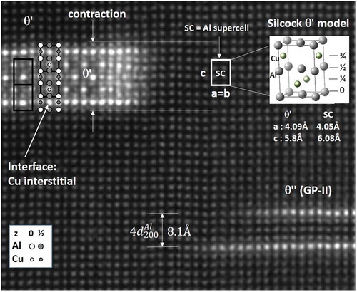
Figure 4. (a) Ω-Al2Cu supercell in aluminium in [1-2-1] projection. (b-c) Two HAADF images of Ω-plates edge-on. In (a), dotted ovals show how (pairs of Cu) columns in Al can merge to yield the (high intensity) corners of the projected real cell. (Al occupy remaining positions.) Orthorhombic (O) and rhombohedral (R) cell are projections of same six-atom cell, relatively rotated. (b) A Ω-platelet structure, spanning 7 {111}Al planes in alloy Al-1Mg-3Cu-0.5Ag (wt%) and two relatively rotated layers (O, R). (c) Lower part of a Ω-precipitate. Corners have double occupation (×2). Right insert shows substitutions in various precipitate phases built by the same cell.
![Figure 4. (a) Ω-Al2Cu supercell in aluminium in [1-2-1] projection. (b-c) Two HAADF images of Ω-plates edge-on. In (a), dotted ovals show how (pairs of Cu) columns in Al can merge to yield the (high intensity) corners of the projected real cell. (Al occupy remaining positions.) Orthorhombic (O) and rhombohedral (R) cell are projections of same six-atom cell, relatively rotated. (b) A Ω-platelet structure, spanning 7 {111}Al planes in alloy Al-1Mg-3Cu-0.5Ag (wt%) and two relatively rotated layers (O, R). (c) Lower part of a Ω-precipitate. Corners have double occupation (×2). Right insert shows substitutions in various precipitate phases built by the same cell.](/cms/asset/14f99e04-73b2-4d3f-9fcf-89322df67c5b/tapx_a_1479984_f0004_oc.jpg)
Figure 5. (a) The interface layer and the immediate Al (111) plane in [111] projection. Al atoms are coloured black. The interface layer is a ‘split’ Al layer, with 2/3 of positions occupied by a small atom (pink, medium-size atoms), like Cu or Zn (ideally 2.87 Å apart) and the remaining positions by a larger atom (Mg, Li, Al). (b) The same in [−211] projection. Compare with .
![Figure 5. (a) The interface layer and the immediate Al (111) plane in [111] projection. Al atoms are coloured black. The interface layer is a ‘split’ Al layer, with 2/3 of positions occupied by a small atom (pink, medium-size atoms), like Cu or Zn (ideally 2.87 Å apart) and the remaining positions by a larger atom (Mg, Li, Al). (b) The same in [−211] projection. Compare with Figure 4.](/cms/asset/141ffa30-71c4-4adb-bc64-aded6b8acdfd/tapx_a_1479984_f0005_oc.jpg)
Figure 6. [1-2-1] Al projection in an alloy Al-8.5Zn-2.2Mg-1.9 Cu (wt.%), along a heavily faulted structure explainable by periodic stacking (in viewing direction) of columns of the same rhombohedral supercell building η and η′ phase [Citation62]. Local fivefold symmetry exists around all the doubly occupied (×2) cell corners. A pentagon shows five rhombohedra sharing a corner, forming a near-perfect pentagonal (icosahedral) symmetry. Lower arrows indicate interface Zn atoms split a {111}Al plane locally outside corners, like shown in . Open/filled circles indicate different plane heights, while the doubly occupied corners have two special heights. Cu is intermixed with Zn.
![Figure 6. [1-2-1] Al projection in an alloy Al-8.5Zn-2.2Mg-1.9 Cu (wt.%), along a heavily faulted structure explainable by periodic stacking (in viewing direction) of columns of the same rhombohedral supercell building η and η′ phase [Citation62]. Local fivefold symmetry exists around all the doubly occupied (×2) cell corners. A pentagon shows five rhombohedra sharing a corner, forming a near-perfect pentagonal (icosahedral) symmetry. Lower arrows indicate interface Zn atoms split a {111}Al plane locally outside corners, like shown in Figure 5(b). Open/filled circles indicate different plane heights, while the doubly occupied corners have two special heights. Cu is intermixed with Zn.](/cms/asset/67f414e2-81d9-49de-80b7-6509190b8db0/tapx_a_1479984_f0006_oc.jpg)
Table 1. Precipitate phases in alloy systems Al-Mg-Si and Al-Mg-Cu.
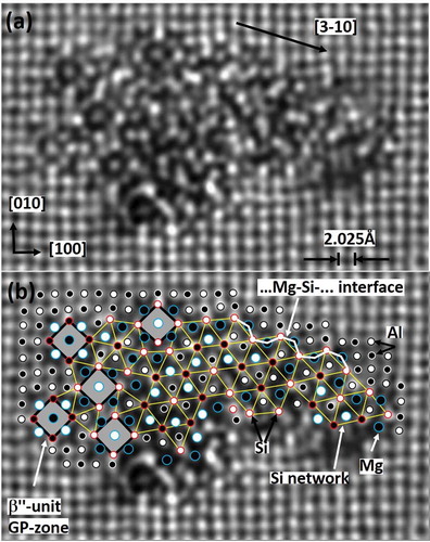
Figure 7. Cross-section of a small β″ precipitate in Al-1.2Si-0.3Mg-0.04Cu, aged 30 mins at 185°C. Four eye-like molecules span a semi-cell. The monoclinic b-axis is parallel with the viewing <001> Al direction. A molecule is comparable with one Al cell (see Figure 8). High intensity columns indicate Cu (also seen at the lower β″ interface).
Figure 8. <001>Al zone with two β″ eyes in projection. (Same alloy as in , but aged 30 days at 90°C). (b) is (a) with overlay. (c) and (d) show higher magnification. Single eyes are not shown. The two eyes connect along a < 320> Al direction, as for β″ (), by triangularly arranged Si columns (Si-network). shows that Mg in the centre slightly lowers energy.
Table 2. DFT calculations showing stability for 12 (infinitely long) GP-zones without/with the interstitial 1D defect, by formation enthalpy (energy change) for 64-atom supercell (4 × 4 × 1 Al cells) and per solute. This means 8 or 9 solute columns per 64 infinite columns. The molecular embedded string is Mg4A4B, where A is Si or Cu, and B is the centre atom (Al, Mg, Cu). ‘D’ in cell composition says the centre column is interstitial (a defect). The solute replaced columns Mg4Cu4 around an interstitial Al column (Al56Mg4Cu4D) yield the most stable GP-zone. Without the defect, Al56Mg4Cu4 ranges second worst. Note that Cu can be in the centre, as has recently been observed for β″ [Citation95].
Figure 9. HAADF image of an Al-3 Mg-1 Cu alloy (wt%) [Citation60], heat-treated 1 min at 170°C. Arrows point out two independent 1D GP-zones consisting of four columns each of Cu and Mg, isostructural to the 1D zones in Al-Mg-Si as shown in , with Si replaced by Cu. Calculations in () indicate Al centre and ratio Mg/Cu = 1.
![Figure 9. HAADF image of an Al-3 Mg-1 Cu alloy (wt%) [Citation60], heat-treated 1 min at 170°C. Arrows point out two independent 1D GP-zones consisting of four columns each of Cu and Mg, isostructural to the 1D zones in Al-Mg-Si as shown in Figure 8, with Si replaced by Cu. Calculations in (Table 2) indicate Al centre and ratio Mg/Cu = 1.](/cms/asset/9a4a2499-4105-4a18-896b-7ad6703f8cf5/tapx_a_1479984_f0009_b.gif)
Figure 10. (a) Structure of S’-MgCuAl2 phase along a-axis (a = 4.05 Å) illustrates column rules. Large to small disks are Mg, Al and Cu. Polygons show five-, four- and and threefold surrounding column symmetry. The two heights in the viewing direction (white and dark fill) align with Al-planes (z = 0, ½). (b) HAADF of <001>Al projection of Al-3Cu-1Mg (wt%) heat-treated 11 days at 170°C, with Al-embedded S’ plate along its coherent a-axis. (c) Detail of particle in (b) partly superposed, showing consistent column arrangement/symmetry around columns across the particle. The same applies to all coherent precipitates in Al-Mg-Si and Al-Mg-Cu system. The interface is a ‘fence’ of alternating Mg and Cu columns.
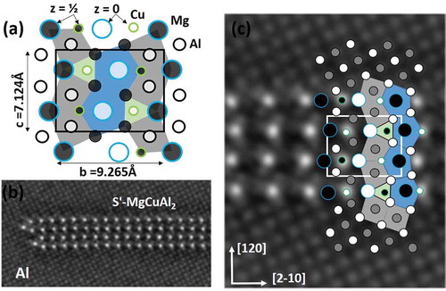
Figure 11. Alloy Al-0.7Mg-0.35Si-0.1Co (at%) aged 67 h at 200°C. (a) A β′ rod demonstrates the Si network with increased intensity for corners (4 Si atoms per 3 in other columns). (b) Overlaid region with β′ interface along <310>Al direction. U1 interphase bridges β′ to the matrix and ends it with the normal Mg-Si alternating column interface. Column rules apply only in the interface of these less coherent phases. In the upper right unit cell of U1, the rhomb signifies a projected octahedron (two pyramids base-to-base) – the basic unit in the Si-network, Mg2Si and diamond Si.
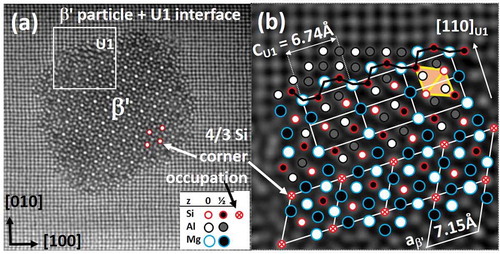
Figure 12. (a) Cross-section of disordered precipitate needle in a commercial 6060 alloy, aged 5 h at 190°C. (b) With suggested overlay. Upper part shows partly coherence along <310>Al. Grey squares are individual β″ molecules (GP-zones). The (projected) Si-network is indicated by yellow lines. Atoms/heights may be inferred by network (Si-columns), spacing, intensity and a consistent column symmetry (Mg: fivefold, Si: threefold and Al: fourfold). The interface reflects that of a general coherent precipitate in Al-Mg-Si; i.e. a surrounding wall of alternating Mg and Si columns along the needle <100>Al direction. Open/filled symbols reflect the two {100}Al plane heights.