Figures & data
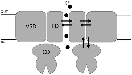
Figure 1. Mechanisms of K permeation through K+ channels. (A) Experimental data from [Citation3] showing the electrophysiological properties of KcsA channels. Left: Current–voltage relationships obtained at varying K+ concentrations. Right: conductance–concentration relationship assessed at two different voltages. (B) Three-dimensional structure of the KcsA channel, as revealed by X-ray crystallography [Citation2]. C) High resolution electron density map of the KcsA selectivity filter, as obtained (under permission) by [Citation4], showing four putative K+ binding sites inside the selectivity filter, and three additional ones immediately outside. (D) Drawing showing the two main K+ permeation mechanisms proposed for the K+ channel, known as soft and hard knock-on. (E) Two different rate models of K+ permeation are shown, together with their prediction in terms of the current-voltage and conductance–concentration relationships. While the classical knock-on type mechanism predicts hyperlinear current–voltage relationships and non-saturating gCs, an association–dissociation model predicts permeation features quite similar to those experimentally observed for K+ channels (cf panel A). (F) Mathematical relationships connecting the kinetic rate constants of a rate model to the energetic profile (U) and the diffusion constant (D). The expression used for estimating the rate constants not involving the binding of K+ ions was derived from the mean first passage time theory, while the expression for the K+ association binding constants was derived from the Smolukowsky equation
![Figure 1. Mechanisms of K permeation through K+ channels. (A) Experimental data from [Citation3] showing the electrophysiological properties of KcsA channels. Left: Current–voltage relationships obtained at varying K+ concentrations. Right: conductance–concentration relationship assessed at two different voltages. (B) Three-dimensional structure of the KcsA channel, as revealed by X-ray crystallography [Citation2]. C) High resolution electron density map of the KcsA selectivity filter, as obtained (under permission) by [Citation4], showing four putative K+ binding sites inside the selectivity filter, and three additional ones immediately outside. (D) Drawing showing the two main K+ permeation mechanisms proposed for the K+ channel, known as soft and hard knock-on. (E) Two different rate models of K+ permeation are shown, together with their prediction in terms of the current-voltage and conductance–concentration relationships. While the classical knock-on type mechanism predicts hyperlinear current–voltage relationships and non-saturating gCs, an association–dissociation model predicts permeation features quite similar to those experimentally observed for K+ channels (cf panel A). (F) Mathematical relationships connecting the kinetic rate constants of a rate model to the energetic profile (U) and the diffusion constant (D). The expression used for estimating the rate constants not involving the binding of K+ ions was derived from the mean first passage time theory, while the expression for the K+ association binding constants was derived from the Smolukowsky equation](/cms/asset/92173efa-952c-48d1-8aac-e8faf8341a76/tapx_a_1978317_f0001_oc.jpg)
Figure 2. Location and function of two distinct gates in model K+ channel pore Cartoon representation of KcvNTS in side-view orientation with two opposing monomers (left). The selectivity filter (SF) gate causes fast flicker gating in KcvNTS with the effect that the full open state is not fully resolved (trace ii). The mutation S42T in the pore helix behind the selectivity filter (S42T: upper part of right panel) slows down fast gating with the result that the full open state of the channel is achieved (trace i). The presence (trace iii) or absence (trace ii) of a long-lived closed state (*) as result of the cytosolic gate depends on presence or absence of S77 in inner transmembrane helix (G77S: lower part of right panel). The cytosolic gate is operated by the formation/breaking of an intrahelical H-bond and the consequent re-orientation of F78. Single channel currents were recorded with symmetrical 100 mM KCl (10 mM HEPES/KOH pH 7.0) in DPhPC bilayers. C and O highlight the closed and open levels, respectively
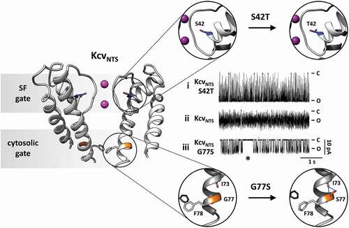
Figure 3. Molecular basis for the noncanonical coupling mechanism in Shaker K+ channel. (A) Intramembrane view of the active state of the voltage sensor domain (VSD) and open state of the pore domain (PD) in a model of Kv1.2, a human Shaker K+ channel homolog (PDB:3LUT). (B) Extracellular view of A showing swapped domains in the channel complex. The zoomed views show the color-coded residues V369, L409, S411, S412, F433, W434 and Y445 that are implicated in the noncanonical mechanism that couples VSD and PD from distinct subunits (also color coded). The upper zoomed views show the physical (and functionally tested) connection between a VSD from one subunit and a PD from a different subunit which is the molecular basis of the noncanonical coupling mechanism. The bottom zoomed views show the same residues but, as they are in the same subunit, they are uncoupled to the S4 segment
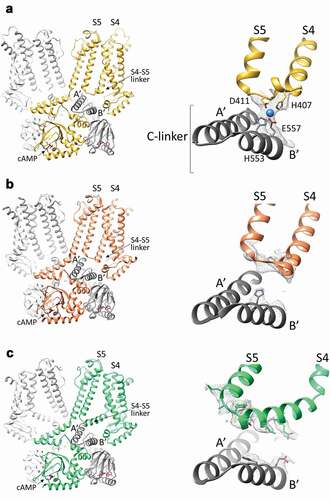
Figure 4. The S4-S5 linker in HCN4 and HCN1 channels. A, Left, structure of the cAMP-bound HCN4 channel tetramer, in a cross-membrane view. For clarity, only two subunits in the tetramer are shown in full (yellow and light grey), while for the other two subunits (dark and light grey), only the cytosolic C-linker/CNBD domains are presented. The transmembrane S4 and S5 helices, the S4-S5 linker connecting them and the first two helices (A’ and B’) of the cytoplasmic C-linker are labelled. Right, ribbon representation of the S4-S5 linker of one subunit (yellow) and the underlying C-linker (A’-B’ helices) of the adjacent subunit (grey) of HCN4. Four residues forming the ion coordination site (tetrad) in HCN4 are shown as sticks and labelled (H407, D411, H553, and E557). The ion coordinated by the tetrad is represented as a blue sphere. The density map for the region of the tetrad is shown as grey mesh. B, Left, structure of the cAMP-bound HCN1 channel tetramer in the resting state (PDB: 5U6P), in a cross-membrane view. For clarity, only two subunits in the tetramer are shown in full (orange and light grey), while for the other two subunits (dark and light grey) only the cytosolic C-linker/CNBD domains are presented. The transmembrane S4 and S5 helices, the S4-S5 linker connecting them and the first two helices (A’ and B’) of the cytoplasmic C-linker are labelled. Right, ribbon representation of the S4-S5 linker of one subunit (orange) and the underlying C-linker (A’-B’ helices) of the adjacent subunit (grey) of HCN1 in the resting state. Shown as grey mesh is the density map for the S4-S5 linker and of the corresponding residues of the HCN4 tetrad located in B’ helix of C-linker. Only the two corresponding histidines forming the ion tetrad HCN4 are shown as sticks as for its side chain there is density. C, Left, structure of the cAMP-bound HCN1 channel tetramer in the activated-like state (PDB: 6UQ), in a cross-membrane view. For clarity, only two subunits in the tetramer are shown in full (green and light grey), while for the other two subunits (dark and light grey) only the cytosolic C-linker/CNBD domains are presented. The transmembrane S4 and S5 helices, the S4-S5 linker connecting them and the first two helices (A’ and B’) of the cytoplasmic C-linker are labelled. Right, ribbon representation of the S4-S5 linker of one subunit (green) and the underlying C-linker (A’-B’ helices) of the adjacent subunit (grey) of HCN1 in the activated-like state. Shown as grey mesh is the density map for the S4-S5 linker and of the corresponding residues of the HCN4 tetrad located in B’ helix of C-linker. The residues of these regions for whose side chains there is density are shown as sticks