
Figures & data
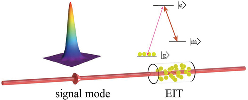
Figure 1. The vee-type (), ladder and lambda (
) structures in three-level system.
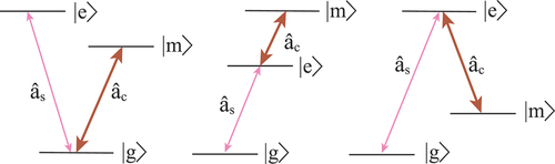
Figure 2. The general EIT system.
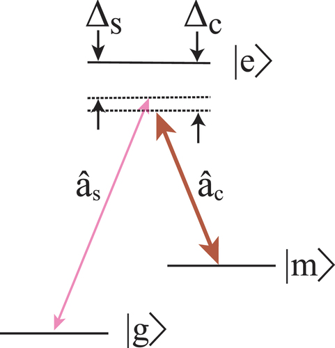
Figure 3. Propagation of a dark-state polariton. (a) The mixing angle is rotated from 0 to . (b) The coherent amplitude of the polariton, light and matter components are plotted. (c) (d) the quantum state is transferred between light and matter, respectively. Reprinted with permission [Citation32].
![Figure 3. Propagation of a dark-state polariton. (a) The mixing angle is rotated from 0 to π/2. (b) The coherent amplitude of the polariton, light and matter components are plotted. (c) (d) the quantum state is transferred between light and matter, respectively. Reprinted with permission [Citation32].](/cms/asset/9b9f022d-0f77-4753-b7a9-7f9819a8e5b4/tapx_a_2060133_f0003_b.gif)
Figure 4. The iteration signal mode by a certain control mode and the efficiency with different pulse shape. Reprinted with permission [Citation35].
![Figure 4. The iteration signal mode by a certain control mode and the efficiency with different pulse shape. Reprinted with permission [Citation35].](/cms/asset/60d16084-59ab-4774-9c4e-6e97a53ba0a2/tapx_a_2060133_f0004_oc.jpg)
Figure 5. The experiment setup for QM in cold atoms. The energy level shows in the bottom left. Reprinted with permission [Citation88].
![Figure 5. The experiment setup for QM in cold atoms. The energy level shows in the bottom left. Reprinted with permission [Citation88].](/cms/asset/7d549030-92a3-410e-9ea7-0bcfd9a3d43f/tapx_a_2060133_f0005_oc.jpg)
Figure 6. The signal mode energy and the retrieved images varies with memory time. Reprinted with permission [Citation94].
![Figure 6. The signal mode energy and the retrieved images varies with memory time. Reprinted with permission [Citation94].](/cms/asset/95ca552f-39ff-4ec9-8adf-93f143542da5/tapx_a_2060133_f0006_oc.jpg)
Figure 7. Experimental setup and energy level scheme of the single-photon QM. (a) Schematic of the experimental optical setup. (b) The memory operation timing shows the MOT sequence and the optimized control laser intensity time-varying profile in each experimental cycle. (c) The atomic energy level scheme of the QM based on EIT. Reprinted with permission [Citation39].
![Figure 7. Experimental setup and energy level scheme of the single-photon QM. (a) Schematic of the experimental optical setup. (b) The memory operation timing shows the MOT sequence and the optimized control laser intensity time-varying profile in each experimental cycle. (c) The atomic energy level scheme of the QM based on EIT. Reprinted with permission [Citation39].](/cms/asset/2be060ef-2531-4fe4-b53a-50f1813078f4/tapx_a_2060133_f0007_oc.jpg)
Figure 8. Experimental setup. the inset shows the atomic level configuration. Reprinted with permission [Citation57].
![Figure 8. Experimental setup. the inset shows the atomic level configuration. Reprinted with permission [Citation57].](/cms/asset/0849fd24-7f8e-4671-9389-5f17677a83ef/tapx_a_2060133_f0008_oc.jpg)
Figure 9. (a) Reversible mapping. Illustration of the mapping of an entangled state of light into and out of a QM. (b) Entangled a pair of photons. (c) Quantum interface for reversible mapping. (d)Entanglement verification system. Reprinted with permission [Citation59]
![Figure 9. (a) Reversible mapping. Illustration of the mapping of an entangled state of light into and out of a QM. (b) Entangled a pair of photons. (c) Quantum interface for reversible mapping. (d)Entanglement verification system. Reprinted with permission [Citation59]](/cms/asset/35e82055-cdea-4c51-b31d-f4f4ed59ec90/tapx_a_2060133_f0009_oc.jpg)
Figure 10. Schematic diagram. Experimental setup. It includes three parts, Part I is the generation system of tripartite optical entanglement; Part II is the transportation of tripartite entanglement to three distant atomic ensembles; Part III is the entanglement verification system. Reprinted with permission [Citation63].
![Figure 10. Schematic diagram. Experimental setup. It includes three parts, Part I is the generation system of tripartite optical entanglement; Part II is the transportation of tripartite entanglement to three distant atomic ensembles; Part III is the entanglement verification system. Reprinted with permission [Citation63].](/cms/asset/59dbb4f4-f2c4-47b9-9076-930fba95321c/tapx_a_2060133_f0010_oc.jpg)