Figures & data
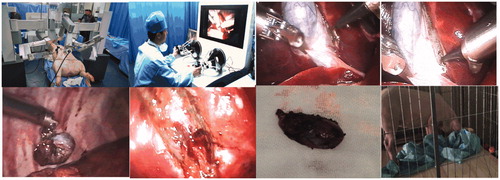
Figure 1. An overview of MIS robotic system: (a) Master console; (b) Slave manipulator.
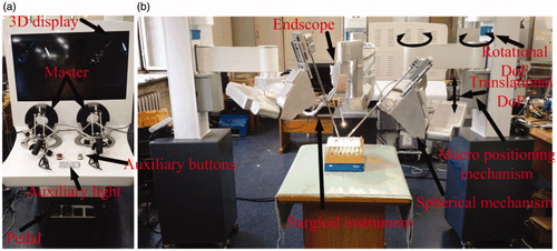
Figure 2. The initial configuration of the manipulator: (a) The manipulator holds surgical instrument; (b) The manipulator holds endoscopy.
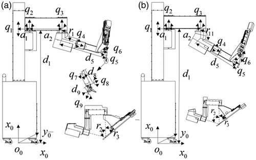
Figure 3. The hybrid simulation model of the endoscopic manipulator: (a) Forward kinematic model; (b) The position calculation module of the OD relative to the CD; (c) Absolute position calculation module of the OD relative to BC; (d) Inverse kinematic model; (e) Forward kinematic model; (f) Position variation of the OD relative to the CD based on BC; (g) Forward kinematic model.
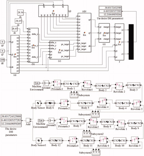
Table 1. The parameters of the endoscopic manipulator.
Table 2. The position vector of the OD relative to the CD.
Table 3. The desire and actual D-H value of motion from the current window to objective window.
Figure 4. The hybrid simulation model of the instrument manipulator.
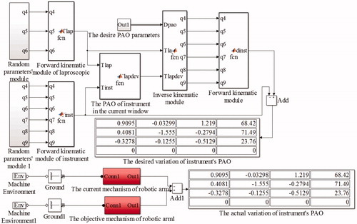
Figure 5. The detailed description of red rectangle shown in Figure 4.
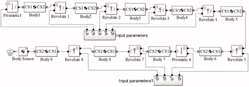
Table 4. The parameters of the surgical instrument manipulator.
Table 5. The required parameters for simulation analysis.
Table 6. The comparison between desired and practical D-value.
Figure 6. Trajectory tracking experiment: (a) Rectangle; (b) Triangle; (c) Pentagon; (d) Circle.
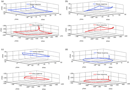
Figure 7. Intuitive control experiments: (a) Rectangle; (b) Triangle; (c) Pentagon; (d) Circle.
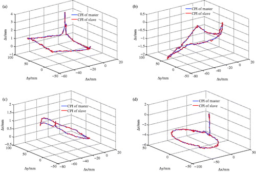
Table 7. The root mean square error of CPI between the master and slave.
Figure 8. Gall bladder removal experiments.