Figures & data
Figure 1. The schematic diagram of the algorithm for removing lumbar vertebrae little joint.
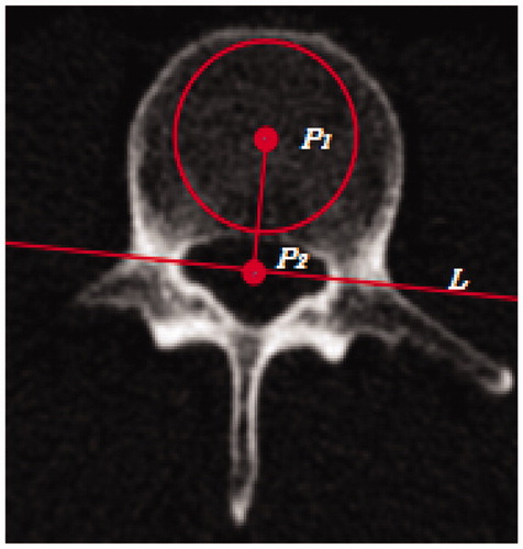
Figure 2. Distribution of the auxiliary points.
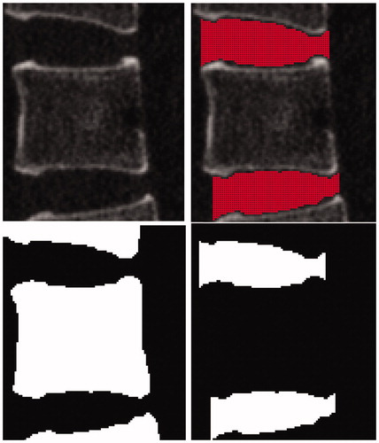
Figure 3. The auxiliary segmentation plane and the correction plane of the vertebra.
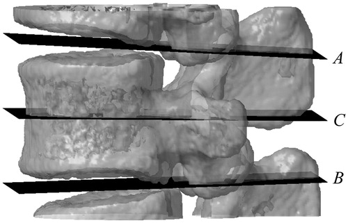
Figure 4. The recognized pedicle area with the largest inner circle.
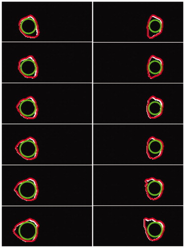
Figure 5. Adjust the path to make it is parallel to the correction plane.
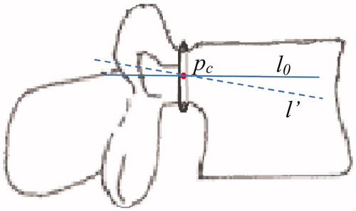
Figure 6. The result of initial path recognition.
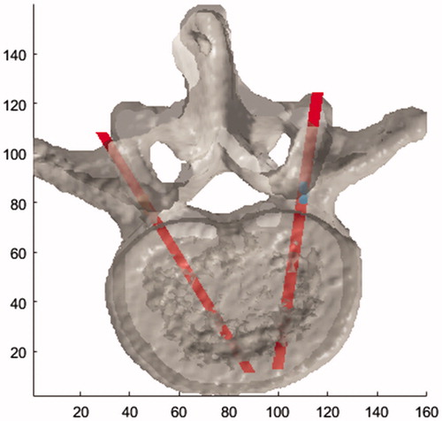
Figure 7. A μCT image shows violent removal of pedicle screw from the bone tissue.
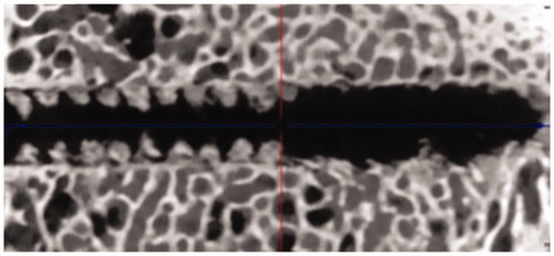
Figure 8. The section area of the path which needs to be calculated.
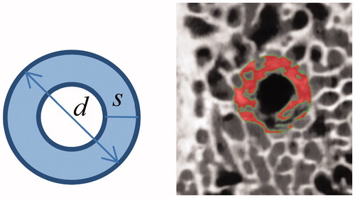
Figure 9. The alter of CT value on the path area and the length of the screws through vertebra.
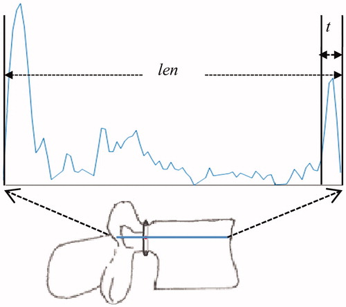
Figure 10. Take plane Mas the segmentation plane to restrict optimization area.
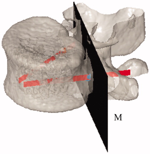
Figure 11. Variable optimization area S.
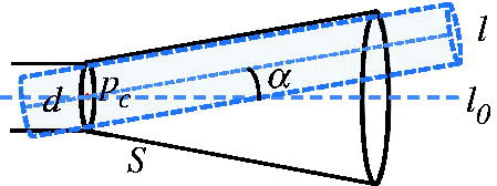
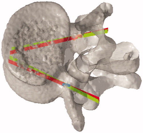
Figure 12. The comparison between initial path and optimization path.