
Figures & data
Figure 1. Wearable video see-through display. The head mounted stereoscopic video see-through display.
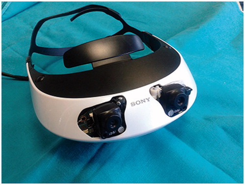
Figure 2. Video see-through paradigm of the augmented reality neuronavigator. The software application merges the virtual three-dimensional surgical planning with the stereoscopic views of the surgical scene grabbed by the stereo rig. Thereafter, the augmented reality stereo frames are sent to the two internal monitors of the visor. Alignment between real and virtual information is obtained by a tracking modality that relies on the localization of at least three reference markers rigidly constrained to the head phantom and whose position in the virtual scene (SRS) is recorded during surgical planning.
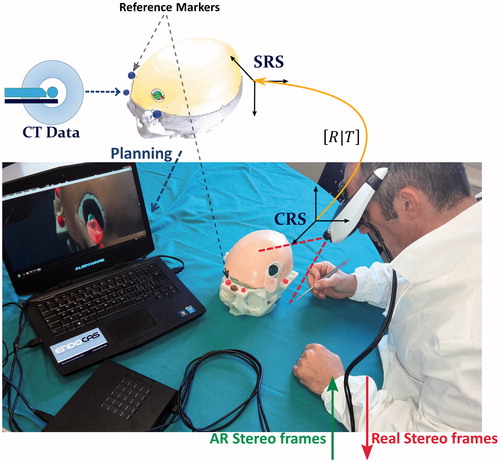
Figure 3. Surgical planning for skin incision and craniotomy. Elaboration of the surgical planning on the three-dimensional rendering of the segmented anatomy, obtained by means of a semi-automatic segmentation software. Left: visualization modalities exploited to depict the planned skin incision and the planned craniotomy. Right: a zoomed detail with enhanced transparency of the surgical planning scene. The size, shape, and location of the craniotomy and of the skin incision were deducted on the basis of the optimal dissection corridor planned for accessing the surgical target whilst avoiding the eloquent area.
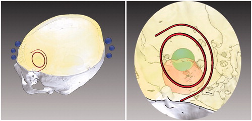
Figure 4. Surgical planning for lesion targeting. Visualization modalities conceived to aid the surgeon in planning the optimal dissection corridor for accessing the surgical target as well as for avoiding the eloquent area: A) 3 D grid effect – The sense of depth is obtained by promoting motion parallax cue through the apparent motional displacement between tumour and background by means of a 3 D grid behind the tumour. (b, c) Occluding and Non-occluding virtual viewfinders – Efficient handling of the occlusion cue between two viewfinders to aid the surgeon in aligning the surgical tool with a predefined trajectory. The first viewfinder indicates the ideal entry point for the surgical tool, whereas the second viewfinder defines the optimal trajectory of dissection. To avoid the occlusion of the real surgical field the second viewfinder, in the Non-occluding modality is moved out of the line of sight of the surgeon, behind the lesion.
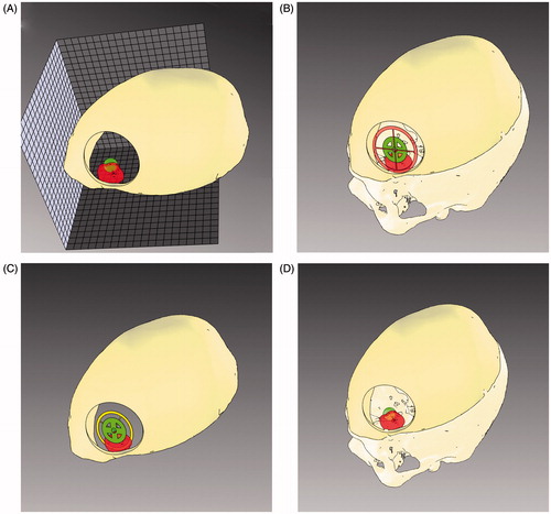
Figure 5. Patient-specific head phantom. A) The skull base is embedded with bilateral frontal lesions both medial to the adjacent eloquent areas (Eloq. area). The inner surface of the skull base presents several housing designed to insert further lesions or eloquent areas. Four lateral shelves served as support for optical reference markers (fluorescent dyed spheres). B) The skull clay vault. C) The liquid polymer used to reproduce the brain was spilled in a complete skull model. After removing the vault, brain perfectly reproduced the details of gross superficial cerebral parenchyma, including: inferior frontal gyrus (IFG), middle frontal gyrus (MFG), superior frontal gyrus (SFG), precentral gyrus (Prec. G), postcentral gyrus (Postc. G.). D) The complete phantom with the vault covered with a skin-like silicon layer.
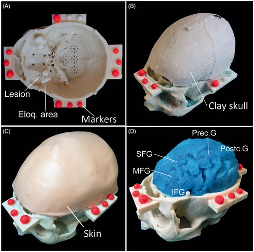
Figure 6. Phase I of the experimental evaluation. Phase I: The four augmented reality visualization modalities as they appear to the user during the evaluation test. A) 3 D grid effect, B) Occluding virtual viewfinders, C) Non-occluding virtual viewfinders, D) Anatomical Occlusions and transparencies.
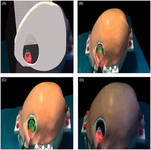
Figure 7. Phase I of the experimental evaluation. Phase II: Augmented reality guided incision of the skin and craniotomy. A) The surgeon marks with a pen the path of the skin incision on the skin following on the augmented reality path (red). B) Scalpel incision. C) After removing the skin incision path, the craniotomy perimeter is displayed and marked with a pen. D) Osteotomy drilling. E) Osteotomy completed: behind the exposed surface of the brain, the surgeon can perceive the position of the target lesion and of the surrounding eloquent area.
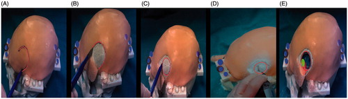
Table 1. Questionnaire results.The central tendency of responses is summarized by using median with dispersion measured by Interquartile range (25°;75°). Statistically significant p-values (<0.05) are highlighted. The last row gives evidence of the modality which resulted more effective and of the significativeness of the evaluation for each modality (bold).
Figure 8. Schematic drawing of the AR visualization modality chosen by the surgeons. The AR visualization modality selected by the surgeons for aiding the targeting of the lesion was obtained by merging the traditional anatomy-based visualization modality that resulted the most effective in evoking depth perception (i.e. Anatomical Occlusions and transparencies) with the one allowing a more accurate definition of the ideal trajectory for targeting the hidden lesion (i.e. Occluding virtual viewfinders).
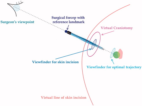
Figure 9. The AR-aided surgical tasks. A: The surgeon first aligns the tip of the dissecting instrument to the center of the dark blue viewfinder he/she sees in the AR scene; B: the surgeon coaxially aligns the back of the surgical forceps to the two viewfinders (dark blue and light blue). The two viewfinders define the optimal trajectory of dissection.
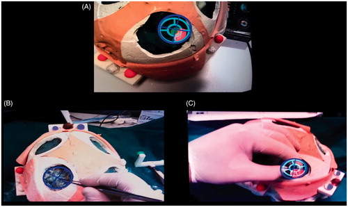
Figure 10. Qualitative comparison between AR and traditional surgical approaches to accessing the artificial lesions. Qualitative comparison between the two approaches to accessing the lesion: augmented reality-based approach (bottom row) vs standard approach (top row). A vs D: by using the augmented reality guidance the size of the skin incision results significantly smaller since the surgeon does not need to expose a large part of the skull vault to targeting the lesion. B vs E: the same concept supports the fact that the osteotomy results wider with the standard approach since the surgeon needs to expose parenchyma sulci and gyri as reference landmarks to navigate towards the lesion. C vs F: the target lesion was reached with both the approaches. However, with the standard approach (C) the eloquent area was considerably exposed (thus implying its possible damaging) and the lesion was not targeted at the center, whereas with the augmented reality approach (F) the lesion was centered and the eloquent area was only slightly exposed.
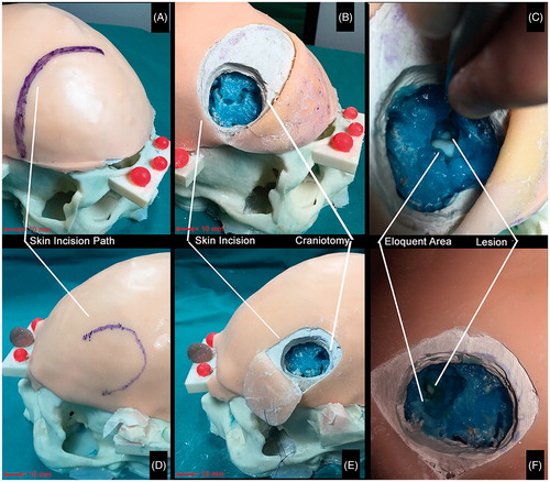
Table 2. Trials results.