
Figures & data
Figure 1. Targeting of the stent graft fenestration site (highlighted with a yellow circle) during an EVAR procedure. Two coordinate systems are represented: a global system (XYZ) in red and a local system (xyz) related to the guiding catheter body in black. Precise targeting requires proper catheter positioning along the longitudinal direction (Z axis), rotation around the catheter main axis (z axis), and bending of the catheter tip (in the yz plane).
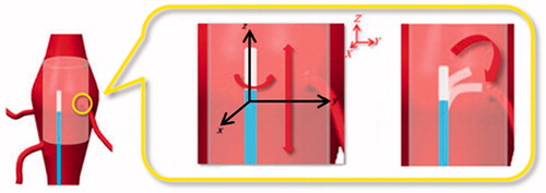
Figure 2. Example of a guiding catheter structure made of three different layers. The reinforcement layer is comprised of a braided mesh characterized by a braid angle that changes the flexibility and torque response of the catheter.
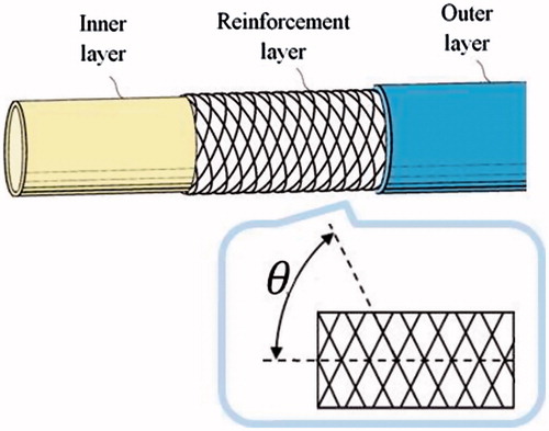
Table 1. Target rigidity values for guiding catheters.
Figure 3. Proposed design solutions for catheter stabilization: (a) ‘Piton-like’ catheter employing a stiff guidewire as a ‘stabilizer’; and (b) a design based on a preformed shape of the catheter body to increase the contact area between the catheter and the graft.
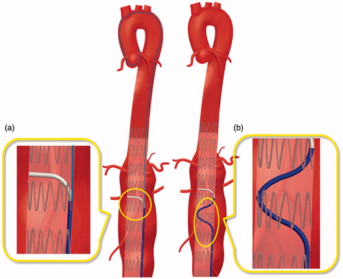
Figure 4. Proposed design solutions for catheter tip bending: (a) a passive solution with a pre-shaped tip and (b) an active solution with a steerable tip.
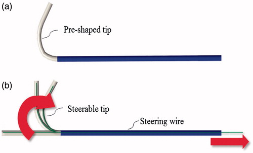
Figure 5. Possible configuration of sensors. Sensor 1 and 2 are positioned according to the method proposed in [Citation11]. Moreover, Sensor 3 is integrated into the catheter tip as a precautionary measure to refine catheter calibration.
![Figure 5. Possible configuration of sensors. Sensor 1 and 2 are positioned according to the method proposed in [Citation11]. Moreover, Sensor 3 is integrated into the catheter tip as a precautionary measure to refine catheter calibration.](/cms/asset/f9369fc8-d341-48d8-8f70-f85280c24012/icsu_a_1358403_f0005_c.jpg)
Figure 6. Preliminary prototypes of the four design solutions to test the stabilization and bending systems. Two pictures are reported for each prototype: a global view of the catheter on the left and a zoom detail of the catheter distal part on the right. The two steerable catheters (Designs A and C) have a handle to actively control bending of the tip.
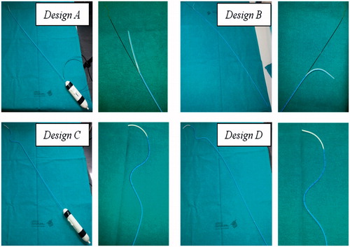
Figure 7. In vitro set-up. A global view of the aorta simulator is shown on the left and a zoom detail showing the plastic tube inserted into the aorta mannequin to simulate the stent graft is shown on the right. Two metal rings are used to indicate the target fenestration sites aligned to the simulated renal ostia (highlighted with blue dotted circles). Note that the plastic tube has no holes at the metal rings.
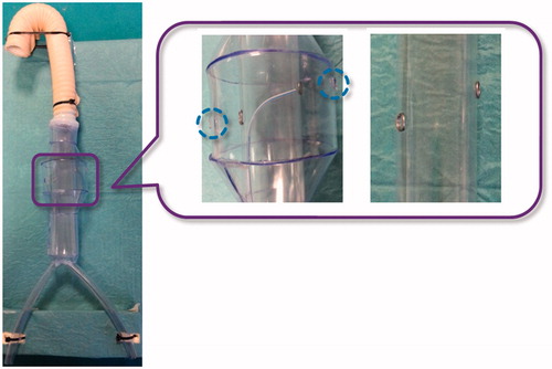
Table 2. Likert Questionnaire: design solution evaluation. For each item, median values with interquartile range (IQR) (25th; 75th) relative to the four proposed design solutions are reported.
Table 3. Likert Questionnaire: general evaluation of stabilization and bending. Median values with interquartile range (IQR) (25th; 75th) are reported.
Figure 8. Possible cross-sectional views ('A1-A1, ' 'A2-A2, ' and 'B-B') at positions A1, A2, and B, of a design A catheter. Four lumens are shown: a central operative lumen (I) for the guidewire tipped laser fiber and the 'stabilizer', two lumens for EM sensors (II), and a lumen for the steering cable (III). The cross section A1-A1 is constant in the catheter blue portion. Then, after the side hole for the 'stabilizer, ' tapering of the central operative lumen (I) as well as the catheter external diameter was started. Two coordinate systems (XAYAZ and XBYBZ, respectively) used for calculation of the second moment of area (Ixx, Iyy, Jzz) at 'A1-A1' and 'B-B' are represented.
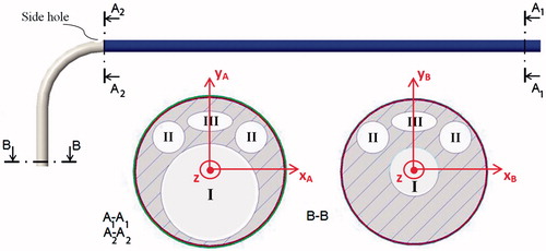
Table 4. Mechanical simulations for two different solutions.