
Figures & data
Figure 1. System components.
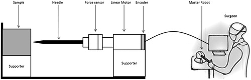
Figure 2. System framework for bilateral control: xm and xs are the displacements for the master and slave robots, Cc and Cs are the control gains, and Zh, Zm, Zs and Ze are the impedances caused by the operator, master robot, slave robot and environment, respectively. Fo and FD are operator’s and the environment’s exogenous input forces and they are independent of the teleoperation system behaviour. Fh represents the interaction force between the operator and master robot, and Fe interaction force between the slave robot and contact environment.
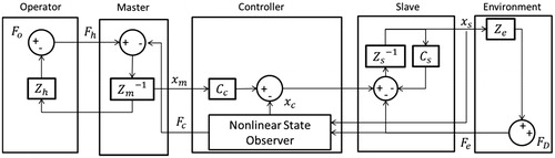
Figure 3. Algorithm of UKF.
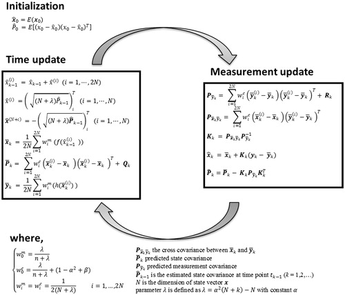
Figure 4. Experimental setup for robotic indentation.
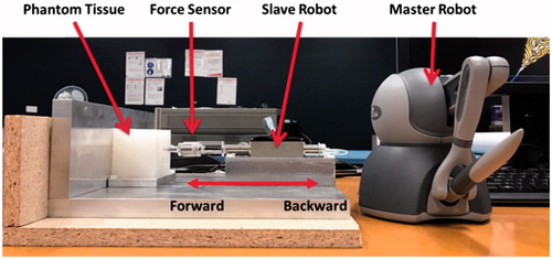
Figure 5. Reconstructed forces by RLS, UKF for the case of robotic indentation: The black dash lines indicate the interaction force (the reference), the red solid lines the reconstructed forces by UKF, and the blue solid lines the reconstructed force by RLS.
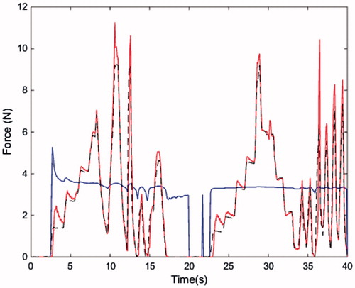
Table 1. Estimation errors of indentation experiment.
Figure 6. Experiment setup for robotic needle insertion into porcine liver.
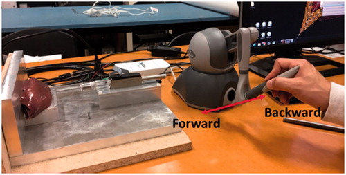
Figure 7. Reconstructed forces by RLS, UKF and RAUKF for the case of robotic needle insertion: The black dash lines indicate the interaction force (the reference), the red solid lines the reconstructed forces by UKF, and the blue solid lines the reconstructed force by RLS.
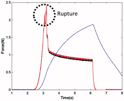
Table 2. Estimation errors of needle insertion into a porcine liver sample experiment.