
Figures & data
Figure 1. Elastic and rigid head phantoms: (a) Elastic phantom, (b) Rigid phantom with tumor models (probe shows the target on tumor model surface).
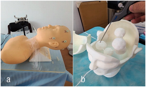
Figure 2. The experimental workflow of LBR method.
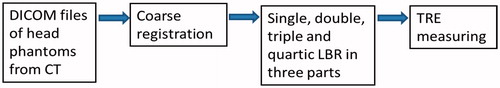
Figure 3. Anatomical landmarks selected as fiducials: (a) Sphenoid-Frontal and Parietal-Temporal parts, (b) occipital part.
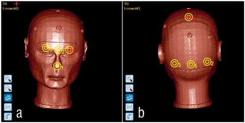
Figure 4. Range of lines for LBR in different areas: row 1 is LBR in Sphenoid-Temporal part: a–d show single(100 points), double (200 points), triple (300 points) and quartic (400 points) lines respectively; row 2 is LBR in Parietal-Temporal part: e–h show single (100 points), double (200 points), triple (300 points) and quartic (400 points) lines respectively; row 3 is LBR in Occipital part: i–l show single once(100 points), double (200 points), triple (300 points) and quartic (400 points) lines) respectively.
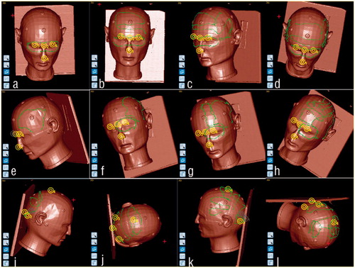
Figure 5. TRE measurement of corresponding targets both in image and patient space (Frames shows that the probe in the image points to the target on the tumor)
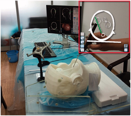
Table 1. Evaluation of TRE by LBR in the elastic and the rigid phantoms (mm).
Figure 6. TRE of sphenoid and frontal tumor phantoms.
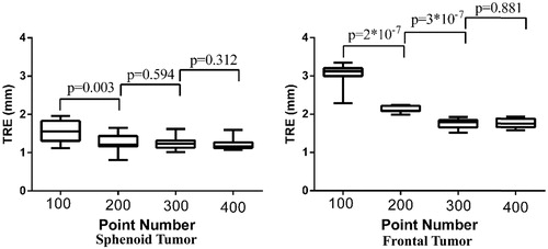
Figure 7. TRE on parietal and temporal tumor phantoms.
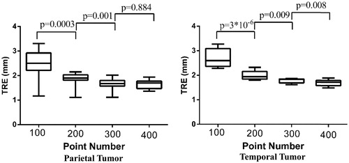
Figure 8. Measurements of TRE of occipital tumor phantom.
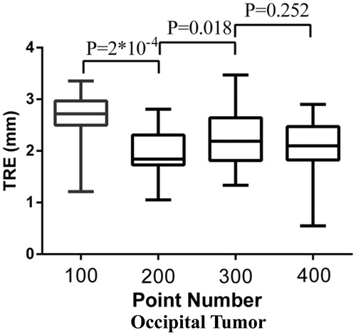
Table 2. FRE of coarse registrations and SRE of LBRs at different areas (mm).