Figures & data
Figure 1. Light ray paths of the initial HMD layout.
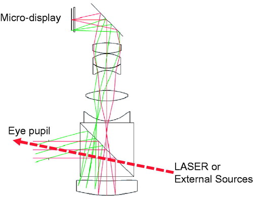
Figure 2. Light paths of the initial HMD with image size ratio adjustment, and (b) that of the HMD with its refracting surface powers of the convex lenses.
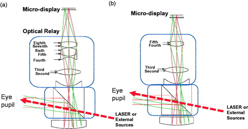
Figure 3. Light paths of the final smallest size HMD.
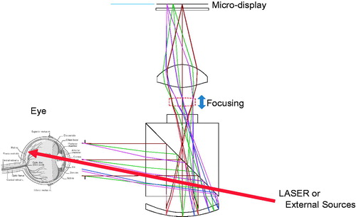
Figure 4. Optical layout for the virtual object of our designed HMD.
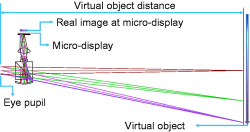
Figure 5. Optical layout and distortion grids of the final smallest size HMD at (a) −1 D, (b) + 1 D, and (c) + 4 D locations.
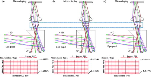
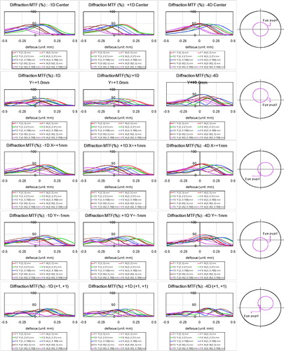
Figure 6. The defocused MTF graphs when the eye pupils are located in the center, + 1 mm in the upward, +1 mm in the right, +1 mm in the downward and diagonal directions of the entrance pupils.