Figures & data
Figure 1. FAST corner detector.
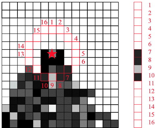
Table 1. The framework of the registration using FastMI.
Figure 2. (a) and (b) are images with opposite intensity. (c) is (a) with Gaussian noise, and (d) is (b) with Gaussian noise and intensity inhomogeneity.
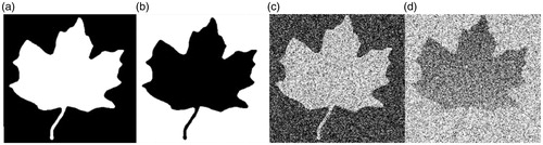
Figure 3. comparison between LMI (top row) and FastMI (bottom row). (a) and (c) are the LMI and FastMI between and with horizontal and vertical shifts, respectively. (b) and (d) are the LMI and FastMI between and .
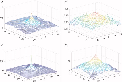
Figure 4. (a) and (b) is the structure regions of and detected by 3 D-FAST, respectively.
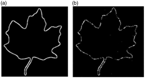
Figure 5. Local deformation (left) and the detailed view of the deformation (right).
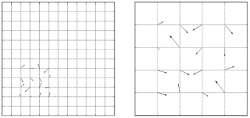
Figure 6. Image after deform (left) and image before deform (right).
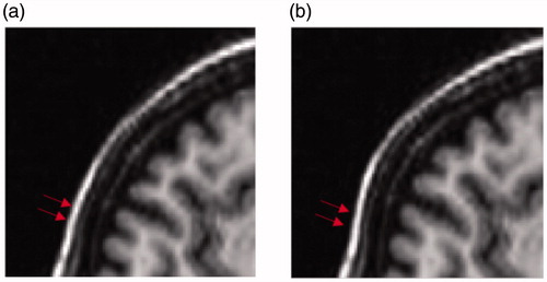
Figure 7. Displacement field from MI and FastMI based registrations. (a) and (b) are the horizontal and vertical displacement of FastMI, (c) and (d) are the horizontal and vertical displacement of MI.
Figure 8. The mTRE of pairwise registrations between T1-T2, T2-PD and T1-PD using CC, LMI and the proposed method. The results of CC are not shown in T1-T2 and T1-PD as their mTRE are too large.
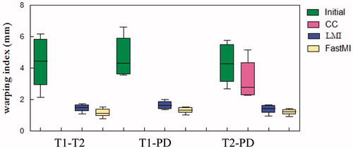
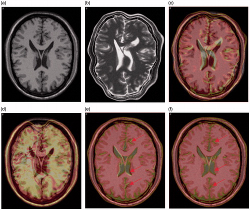
Figure 9. Visual comparison of registration accuracy in the first case of T1-T2 registration. (a) and (b) are the original 90th T1 slice and the artificially deformed T2 slice in registration, respectively. (c) is the result of overlaying the 90th slice of the moving image in (b) on the 90th slice of fixed image in (a) before registration. (d), (e) and (f) are the overlaying after registration with CC, LMI and the proposed method, respectively.