
Figures & data
Figure 1. Spiral CT examination with the navigation board base, as indicated by an arrow.
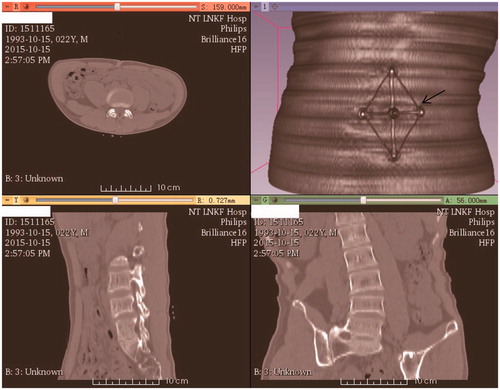
Figure 2. Rigid registration between the reconstructed (rough) and virtual standard (smooth) models showing the puncture path (long cylinder). (a) Registration; (b) Puncture path.
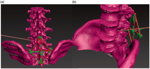
Figure 3. The reverse board root (arrow) and base. The toothed protuberance is used to avoid transformation and rotation between the base and the root.
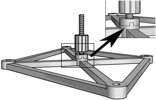
Figure 4. Designation of the reverse board (blue) and the needle path. (a) Design of the reverse board. (b) The needle cannel.
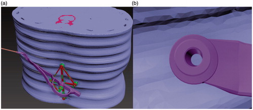
Figure 5. The reverse board and the whole instrument. (a) The reverse board. (b) The whole instrument, which consists of three parts.
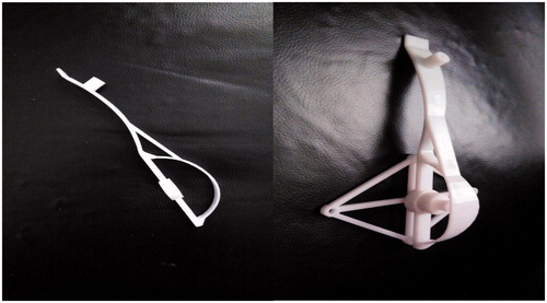
Figure 6. Clinical check under X-ray guidance. (a) Attachment of the board. (b) The five electrode patches (concentric circles) and the puncture results.
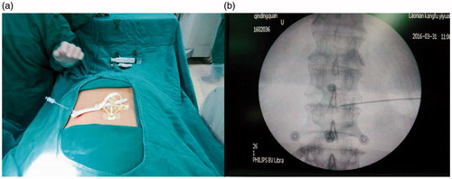
Table 1. Operative duration and intra- and post-operative complications with the use of a customized reverse board.
Figure 7. Dynamic structure design of the reverse board. P1 is the pressure from the puncture; P2 is the stress induced by P1; and F1 is the tension stress of the beam reinforcement.
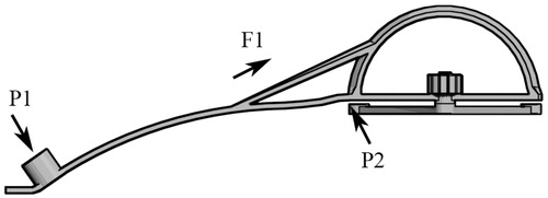
Figure 8. The nut was 3% larger than the whorl on the X-Y (horizontal) plane.
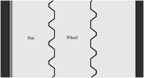
Table 2. The X-Y size ratio and match status between the nut and whorl.