
Figures & data
Table 1. Comparison between EMTS and OTS.
Figure 1. Behaviour of magnetic field for different current values and for wire diameter of
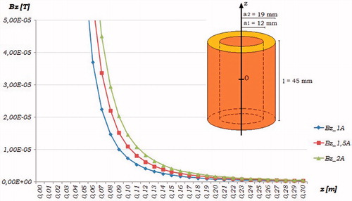
Table 2. Parameters for resonance condition.
Figure 2. Comsol simulation of magnetic flux for coils EMTS.

Figure 3. Arrangement of Transmitting coils EMTS.
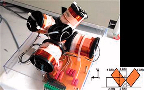
Figure 4. Experimental set-up for the proposed system.
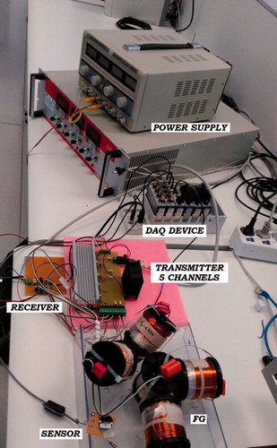
Figure 5. Block diagram of experimental set-up for EMTS with Look-Up-Table.
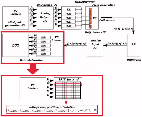
Figure 6. Kuka robot with sensor and FG.
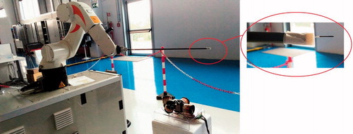
Figure 7. Spectral components of sensor signal with transmitting coils turned off and sensor palced at 60 cm from FG.
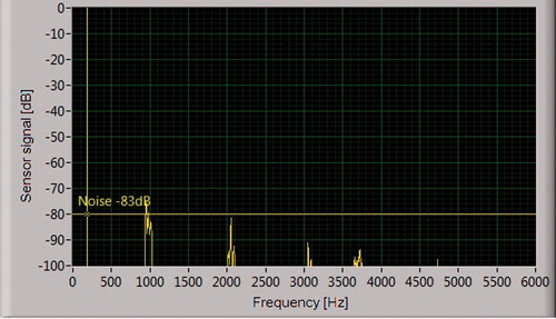
Figure 8. Spectral components of sensor signal with transmitting coils turned on and sensor placed at 60 cm from FG.
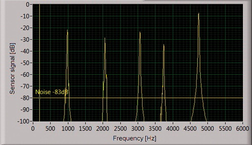
Figure 9. Voltage sensor signal plane scans with a sensor distance from FG of
and transmitting coils turned off.
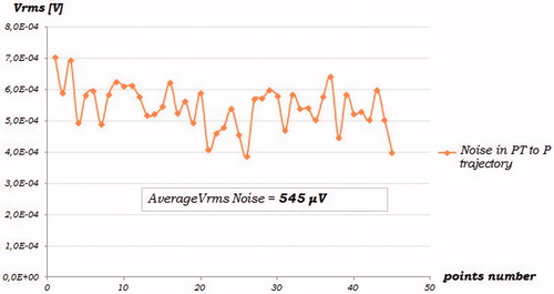
Figure 10. Voltage sensor signal for the 5 consecutive scans of xy plane with sensor distance from FG of 1 m.
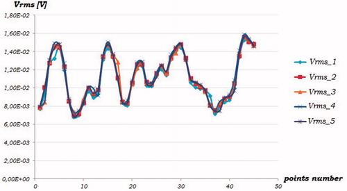
Figure 11. Tracked volume for calibration test.
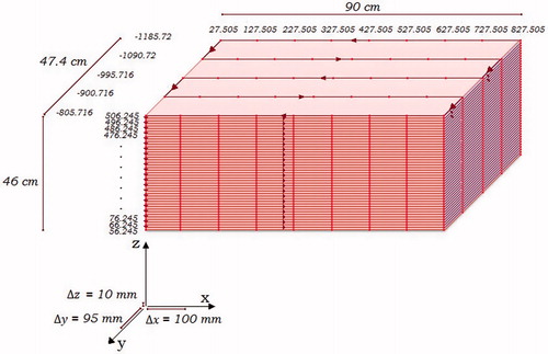
Figure 12. Behaviour sensor signal for different test cases.
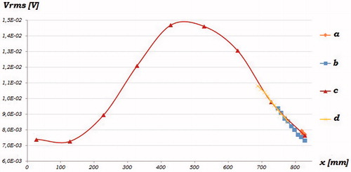
Table 3. Repeatability error.