
Figures & data
Figure 1. Screw trajectories were designed on 3D lumbar models.
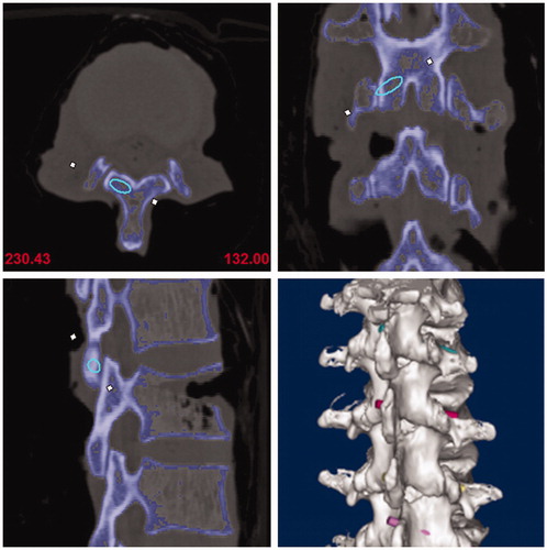
Figure 2. Translaminar facet joint screw guide was designed including matching, connecting and channel parts.
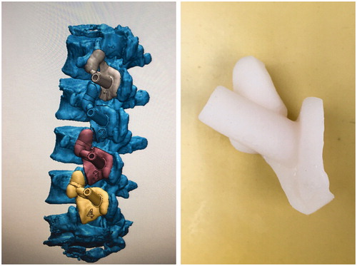
Figure 3. Actual screw trajectories were created on specimens with a 3.2 mm drill and 3.2 mm polylactic acid rods were inserted in to bone tunnels.
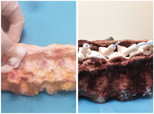
Figure 4. Post-operative and pre-operative 3D lumbar models with actual and planed trajectories were coincided in the same coordinate system.
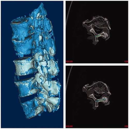
Table 1. The deviation about starting point, tail angle and submergence angle between designed and actual trajectories.