Figures & data
Figure 1. (a) Binucleate cell micrograph; (b) the approximate model; (c,d) the 2D and 3D phase distribution along y axis; (e,f) the 2D and 3D phase distribution along z axis.
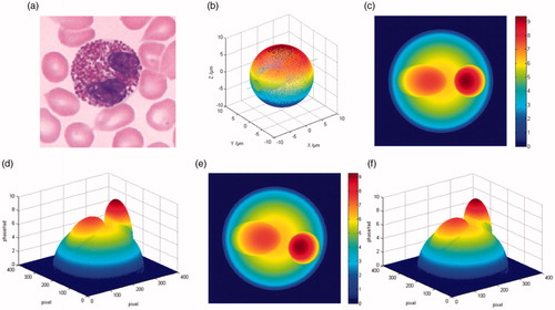
Figure 2. Schematic diagram of the reconstruction algorithm.
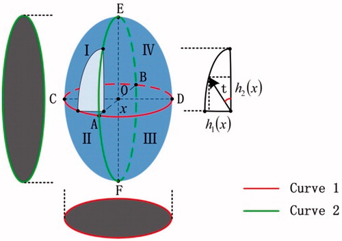
Figure 3. Flowchart of geometric rotation reconstruction method.
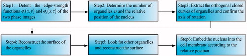
Figure 4. Binuclear cell contour images. (a) The edge-strength of the phase image in x-z plane, (b–d) the contours of the cell membrane, ellipsoidal nucleus and spherical nucleus, (e–h) the corresponding results in x-y plane.
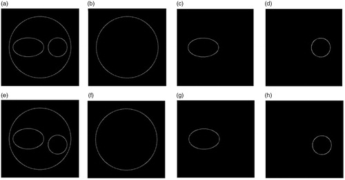
Figure 5. Dinuclear cell reconstruction results by geometric rotation algorithm. (a–c) The 3D surfaces of the cell membrane, ellipsoidal nucleus and spherical nucleus; (d) 3D complete surface of the cell.
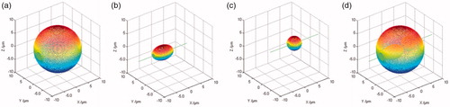
Table 1. Reconstruction errors of each part of the cell.
Figure 6. Principle of experimental setup. LS: light source; FL: frosted lens; OF: optical filter; A: aperture; M: mirror; MO: microscopy objective; BS: beam splitter.
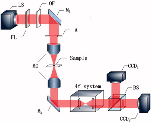
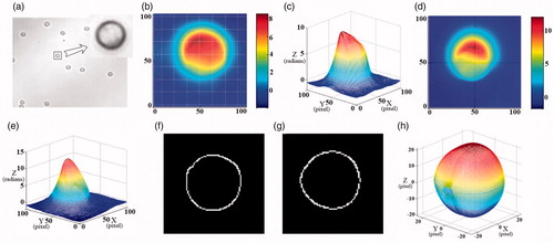
Figure 7. (a) The bright field micrograph of the neutrophil; (b–d) the 3D unwrapped phase images of different neutrophil.
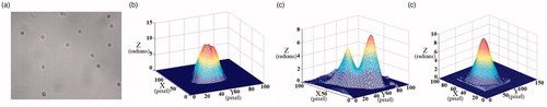
Figure 8. (a) The bright field micrograph of the neutrophil; (b,d) the 2D unwrapped phase images along x and y axes; (c,e) the 3D unwrapped phase images corresponding to (b,d,f,g) the edge-strengths of the phase image in x-z and y-z planes, (h) 3D reconstruction result of the cell.