Figures & data
Figure 1. The model manufacture process. We collect CT data (DICOM files) and then process it with several software including Mimics, 3ds Max, Geomagic Studio, Mudbox, and Meshmixer to obtain the fixed digital model. Finally, we use a 3 D printer to print the model.
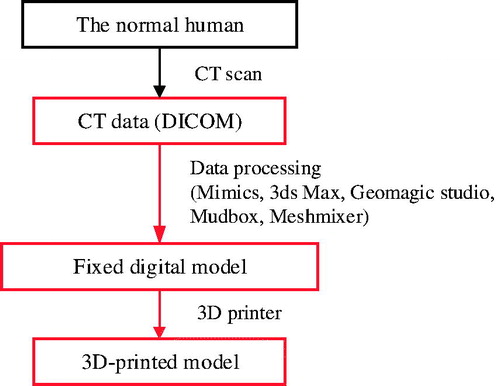
Table 1. Summary of main problems and corresponding solutions.
Figure 2. Set the thresholding value. When the CT scan file is uploaded, we select Menu bar > Segmentation > Thresholding, and, for the data, we set the minimum value as 226 (Bone(CT)) to get the required part of the skull model. The thresholding result is saved as a new mask automatically.
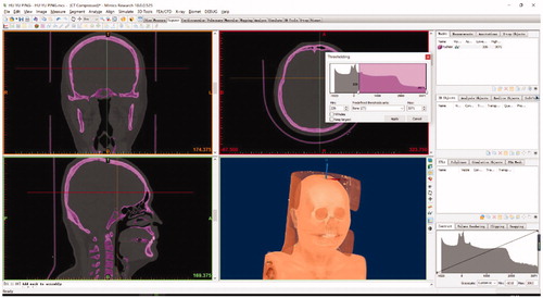
Figure 3. Delete the unwanted part of the model. We select Menu bar > Segment > Edit Mask in 3 D and use the “Lasso” to choose the unrequired parts, such as the vertebra. Then, we select “Remove” to delete it.
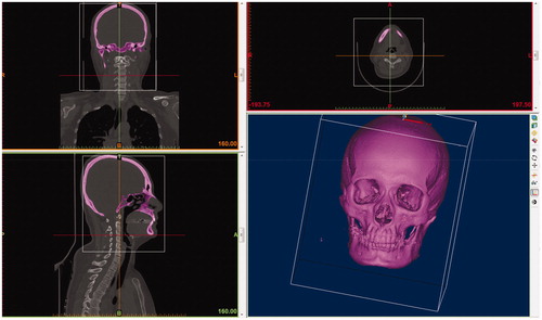
Figure 4. Repair the holes. a) The purple parts in the red circle should be connected. The CT scanning and thresholding value setting may cause some missing parts of the digital model. b) Using Menu bar > Segment > Edit Masks and selecting “Circle” with reasonable size and selecting “Draw” to connect the part on the left. c) Using the same steps as b) to repair the part on the right. d) the complete slice. Since the skull is stereoscopic, we have to “Draw” the missing parts slice by slice.
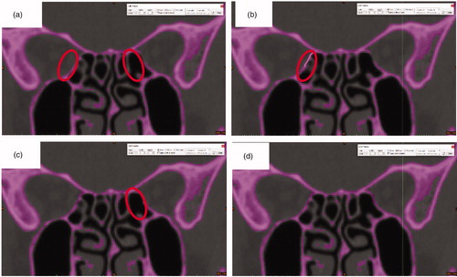
Figure 5. Cut the top part. a) Select the “Slice” tool; Move the cursor to a suitable place; b) Selecting “Remove the top” to delete the skull cap.
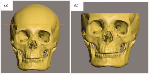
Figure 6. Repair the top. a) Use Fill Holes > Bridge in the edge of the skull cap, then use the Fill Holes > Fill All to repair; b) the surface is level now.
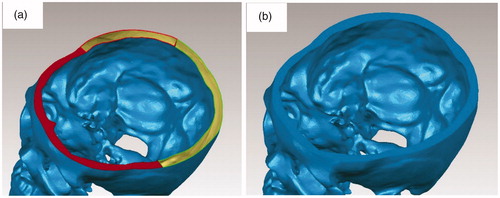
Figure 7. Repair the hole in the surface. a) There is a hole in the red circle; b) We select the hole and the surroundings; c) We delete the hole and make it a bigger hole; d) We select Fill Holes > Fill All to repair the big hole.
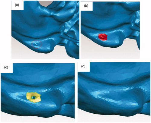
Figure 8. Improve the quality of the model. We select Polygons > Repair > Remesh to retriangulate a polygon mesh to produce a more uniform tessellation. Then we select Polygons > Smooth > Relax to smooth a polygon mesh by minimizing angles between individual polygons, selected Polygons > Repair > Decimate to reduce the number of triangles without reducing surface detail or changing color.
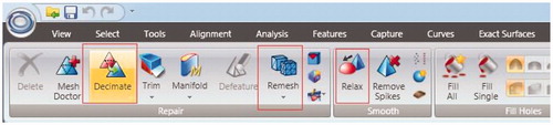
Figure 9. The model with a better quality and smooth surface.
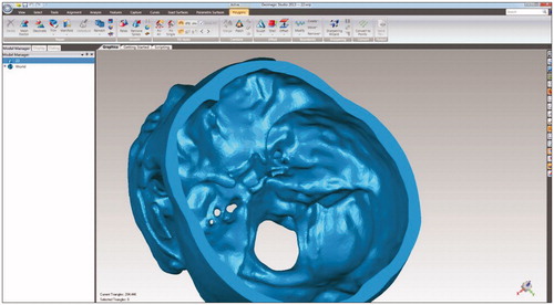
Figure 10. Make the features more obvious. a) The original digital model before manipulation in the Mudbox; b) We deepen the holes, such as supra-orbital foramen and infra-orbital foramen and the cheek part, which are not obvious before the operation; c) We repair the anterior clinoid and make them more obvious; d) We create two mastoid processes. (The size of anterior clinoid in the digital model is too small to show and to print accurately).
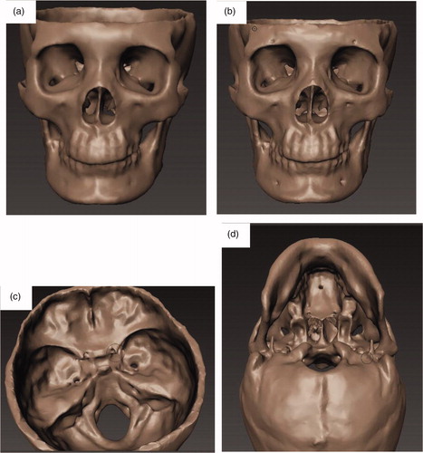
Figure 11. Review the digital model in Meshmixer and make sure that we can print it. If there are some defects remaining, we have to go back to the previous steps to repair them.
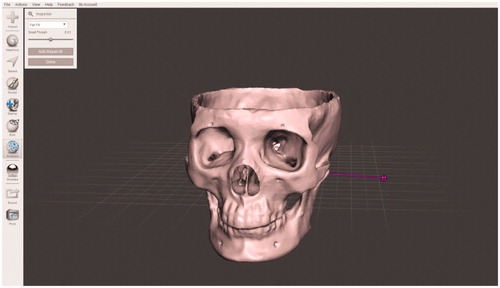
Figure 12. Photos of the cadaveric skull and 3D printed skull. a) Cadaveric skull is shown in frontal, left, right and anterior views, respectively. b) The 3D printed skull is shown in frontal, left, right and anterior views, respectively.
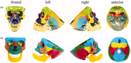
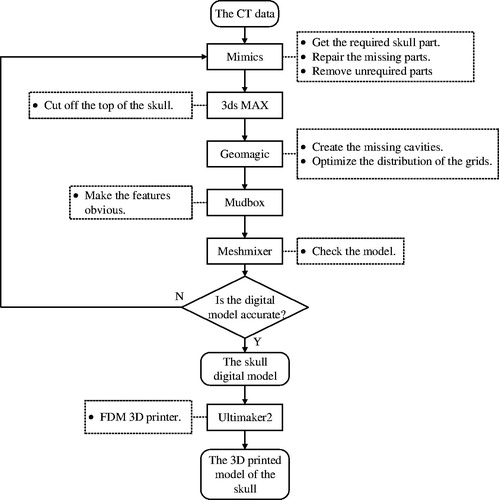
Figure 13. Summary of the workflow. We use five 3D manipulation tools to complete this procedure. We use Mimics to read the data and repair the model by adding the missing parts, use 3ds Max to cut off the top part of the skull, use Geomagic Studio to fix holes in the surface and automatically repair the imperfections in a polygon mesh, use Mudbox to make the features more obvious, and use Meshmixer to check the model. After these operations, the model is ready for printing.