Figures & data
Figure 1. The construction workflow of rapid prototyping navigation template. (a) The coronal and sagittal plane of 3D models of C2–C7. (b) The confirmation of C2 channels to ensure that pedicle screw pass through the center of pedicle without penetrating the cortical bone. (c) The design of navigation template of C2 via the location of screw channels. (d) The confirmation of C3–C7 pedicle screw channels. (e) The design of navigation template of C3–C7 via the location of corresponding screw channels. (f) The physical navigation template and vertebra model.
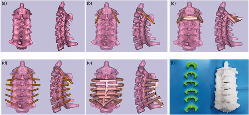
Figure 2. Four different design types of rapid prototyping navigation template. (a) Group 1 with two-level navigation template. (b) Group 2 with one-level bilateral template. (c) Group 3 with one-level unilateral template. (d) Group 4 with one-level point-contact template.
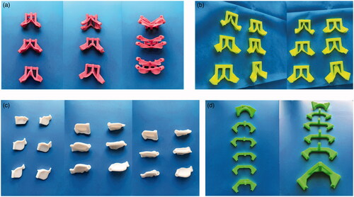
Figure 3. The surgical procedure of pedicle screw insertion with the assistance of rapid prototyping navigation template. (a) The navigation templates fit closely to the posterior surface of corresponding vertebral body. (b) A high-speed drill bit was used to drill channels through navigation template. (c) The cervical specimen and corresponding physical vertebra model. (d) Pedicle screw insertion into the cervical specimen through designed screw channels.
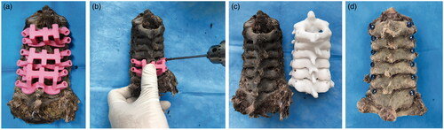
Figure 4. The comparison among five groups of their accuracy.
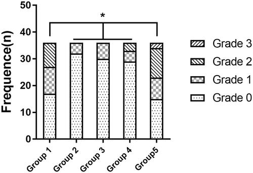
Table 1. Number of pedicle screws perforation and accuracy of screw placement among five groups.
Figure 5. The comparison of operation time among five groups.
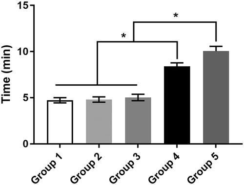
Table 2. The comparison of operation time among four different types of rapid prototyping navigation template groups and no template group.
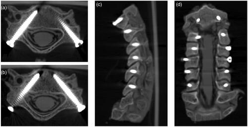
Figure 6. Postoperative CT scan showed positions of cervical pedicle screws with the assistance of one-level bilateral navigation template. (a and b) C4 pedicle screws classified as Grade 0 (axial plane). (c and d) C3 pedicle screws classified as Grade 0 (right) and Grade 1 (left) (axial plane). (e_ C2–C7 pedicle screws from sagittal plane. (f) C2–C7 pedicle screws from coronal plane.
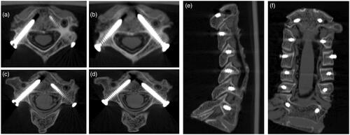
Figure 7. Postoperative CT scan showed positions of cervical pedicle screws with the assistance of two-level navigation template. (a) C5 pedicle screws classified as Grade 2 (left) (axial plane). (b) C5 pedicle screws classified as Grade 0 (right) (axial plane). (c) C2–C7 pedicle screws from sagittal plane. (d) C2–C7 pedicle screws from coronal plane.