Figures & data
Figure 1. Unicycle Kinematics Model. axyz is the inertial coordinate system; u1 represents the feed movement of the flexible steerable needle; u2 represents the rotation movement of the flexible steerable needle; a1y1z1 is the coordinate system of the needle tip at t1, a2y2z2 is the coordinate system of the needle tip at t2; o1 is the arc trajectory of the flexible steerable needle at t1, the radius is r; o1 is the arc trajectory of the flexible steerable needle at t2, the radius is r; ωx represents the rotational angular velocity of the needle tip along the x-axis of the inertial coordinate system.
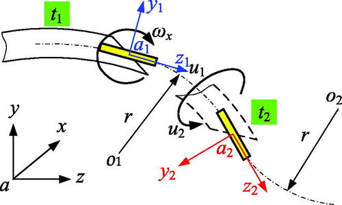
Figure 2. Elastic changes in various path forms. (a) RR path form; (b) RL path form; (c) LR path form.
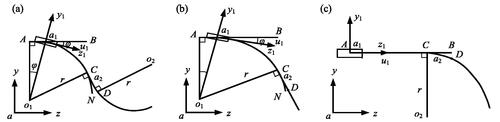
Figure 3. Path optimization using “Markov” decision-making process. (a) Before decision; (b) After decision.
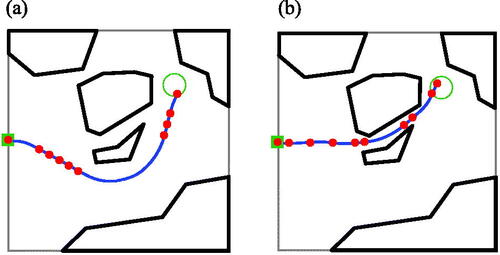
Figure 4. Path optimization using reachable probability density function. (a) Reachable probability density function; (b) Path optimization result.
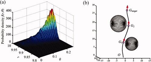
Figure 5. Puncture planning of three-dimensional obstacle environment. (a) Stop-turn; (b) Spiral line.
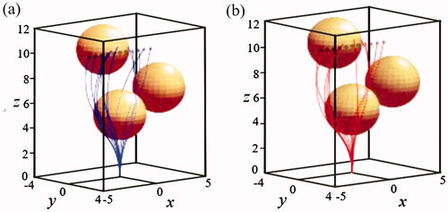
Figure 6. The strategy of needle tip reaching multiple targets. (a) 2D environment adjustment strategy; (b) 3D environment adjustment strategy.
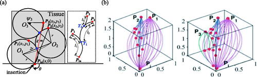
Table 1. Path planning algorithm based on numerical calculation.
Figure 7. RRTs algorithm proposed by Xu. (a) Front view; (b) Top view.
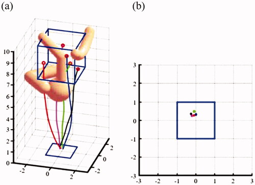
Figure 8. Patil’s improved RRT algorithm. (a) Front view; (b) Side view.

Figure 9. Planning strategy based on risk level. (a) Test 1; (b) Test 2.
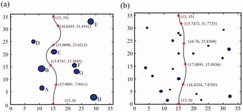
Table 2. Path planning based on search algorithm.
Figure 10. Path planning based on artificial potential field method.
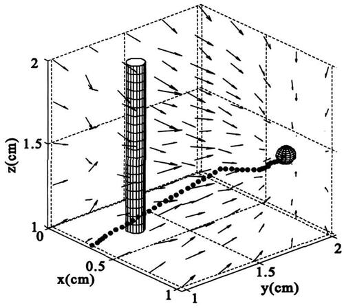
Table 3. Path planning based on other algorithms.
Figure 11. RSPR 6-DOF parallel robot control system.
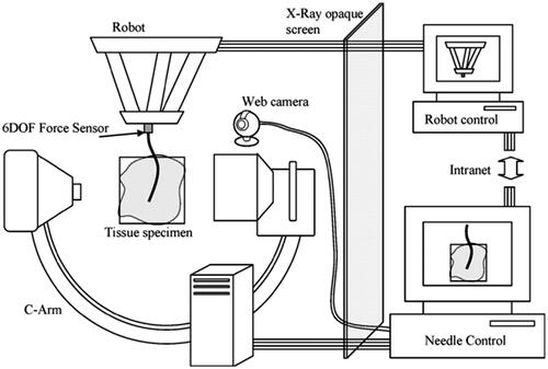
Figure 12. CT image overlay system for flexible steerable needle insertion process. (a) Overall system figure; (b) CT image identified by localization of bone biopsy.
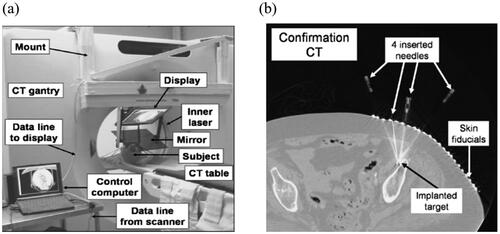
Figure 13. MRI-based FSNP equipment.
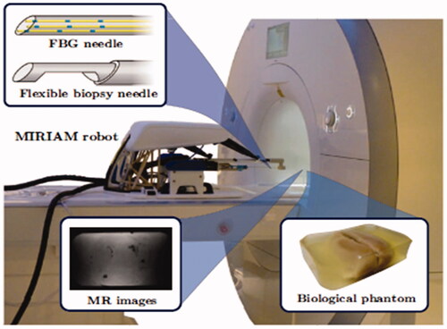
Figure 14. Three-dimensional ultrasound guided robot puncture needle placement system. (a) Experimental institution; (b) 3D ultrasonic interface.
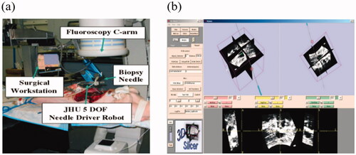
Figure 15. Diagram of closed-loop ultrasound image control system with updated stiffness.
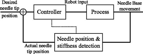
Figure 16. Comparative analysis. (a) Open loop; (b) Closed loop; (c) Closed loop with updated stiffness.
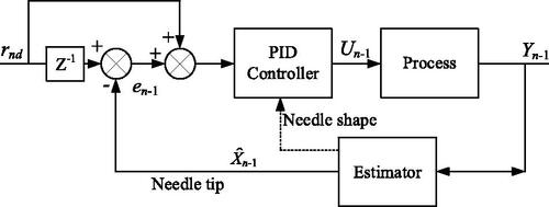
Table 4. Performance comparison of various ways of navigation.
Figure 17. Needle tail puncture control block diagram.
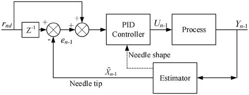
Figure 18. Force/position hybrid control block diagram.
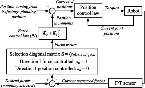
Figure 19. Control block diagram of rotation feedback compensation based on torsion deformation model.
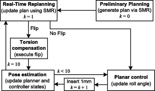
Figure 20. Model of needle body of flexible steerable needle reconstructed by FBG sensor.
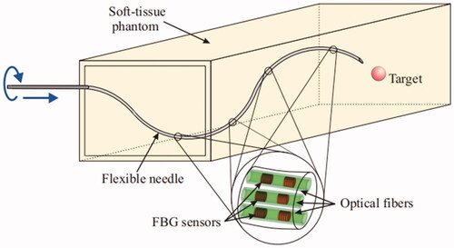
Figure 21. Collaborative puncture robot.
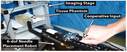
Figure 22. Diagram of magnetic navigation FSNP (a) Device; (b) Process 1; (c) Process 2.
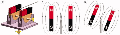
Figure 23. Pre-bent coaxial needle tube.
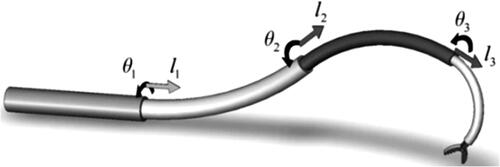
Figure 24. Pre-curved solid needle. (a) bevel tip needle; (b) Pre-curved needle.
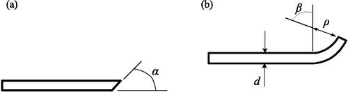
Figure 25. Flexible steerable needle with bevel tip and multiple chain needles.
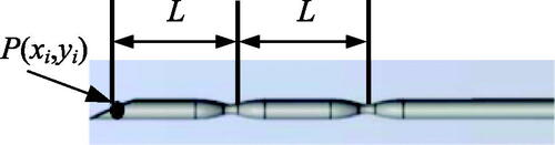
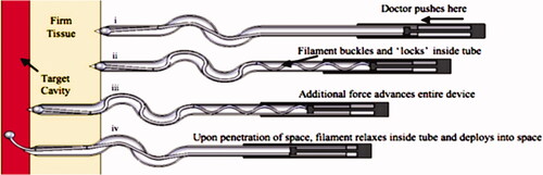
Figure 26. Flexible puncture needle with mechanical clutch device.