Figures & data
Figure 1. (a) Preoperative antero-posterior long-leg standing radiograph. (b) The schematic illustration of the joint orientation angles. The vertical black solid line represents mechanical axis. The bent dotted line indicates the apparent location of the tibial anatomical axis.
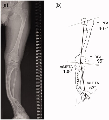
Figure 2. The standard lateral radiograph of the left lower leg. White solid lines indicate the apparent location of the tibial anatomical axes. Two white dashed lines indicate approximate location of two inflection points in the AP view.
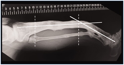
Figure 3. The schematic diagram showing the overall workflow. The processes for osteotomy planning shown in the gray box were performed by a 3D modeling workstation. IMN: Intramenudally nail.
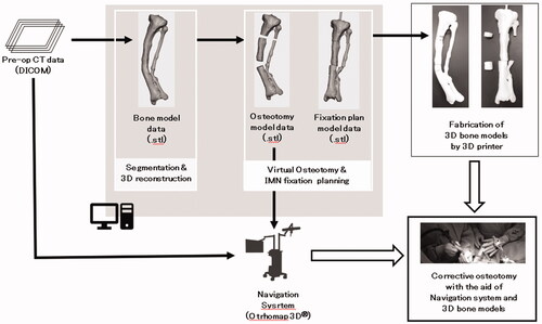
Figure 4. (a) The preoperative 3D model data of the left tibia. (b) The postoperative 3D model data of the left tibia. (c) and (d) are photographs of preoperative and postoperative 3D printed model of the tibia, respectively.
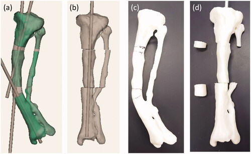
Figure 5. The screenshot of the navigation system during surgery. Osteotomy planes and post-osteotomy models showing the intramedullary nail route were superimposed on the CT image data of the patient’s tibia.
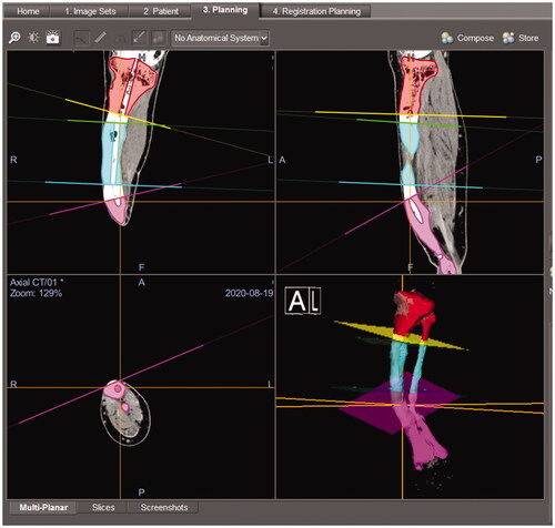
Figure 6. Rehearsal of the navigation system using a patient tibia model.
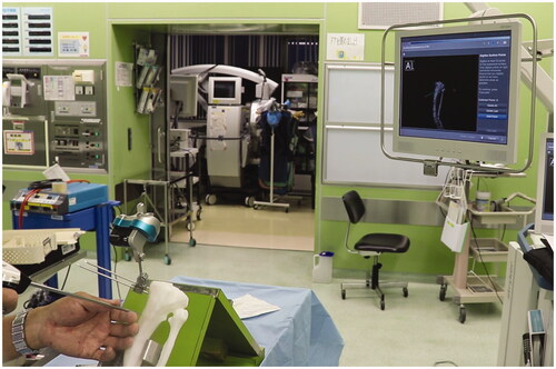
Figure 7. (a) Tibial osteotomy using the navigation system. (b) One of the resected bone fragments and a corresponding bone model. The actual resected bone fragments are smaller than the model for the width of the burr bit.
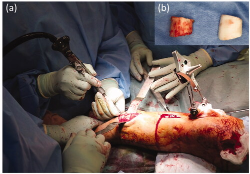
Figure 8. After completion of the osteotomy, we perforated the closed medullary canal visible in the osteotomy cross-section with reference to the bone model and created the intramedullary nail route.
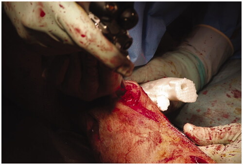
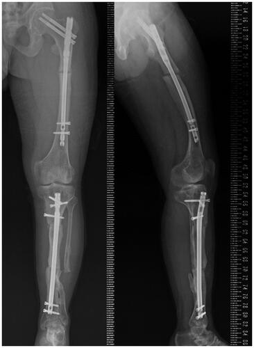
Figure 9. Postoperative long-leg standing radiograph of the left lower leg in antero-posterior and lateral views.