
Figures & data
Figure 1. The design of screw entry points and channels of the sacroiliac joint. (A, B): upper view of three sacroiliac screw channels; (C, D): anterior view of three sacroiliac screw channels; (E, F): posterior view of three sacroiliac screw channels.
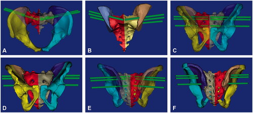
Figure 2. 3D printing guide plates for sacroiliac screws insertion. (A, B): guide plates were designed based on the selection of posterior superior iliac spine; (C): solid diagram of guide plates; (D): guide plates fitting assisted sacroiliac screws insertion.
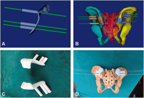
Figure 3. CT scan was used to evaluate the accuracy of sacroiliac screws insertion. (A): Measurement of the anterior and posterior offset angles (α) on cross section. The red solid line represented the preoperative simulated screw channel axis, and the black solid line represented actual screw channel axis; (B): Measurement of the upper and lower offset angles (β) on the coronal plane. The red solid line represented the preoperative simulated screw channel axis, and the black solid line represented actual screw channel axis.
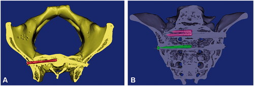
Table 1. Comparison of the anterior and posterior offset angles of actual screw channels and the simulated screw channels in cross section and the upper and lower offset angles in coronal plane.