Figures & data
Figure 1. (a,b) Microstructure and (c,d) grain size distribution of the original (a,c) pure Mg plate and (b,d) AZ31 Mg alloy plate.
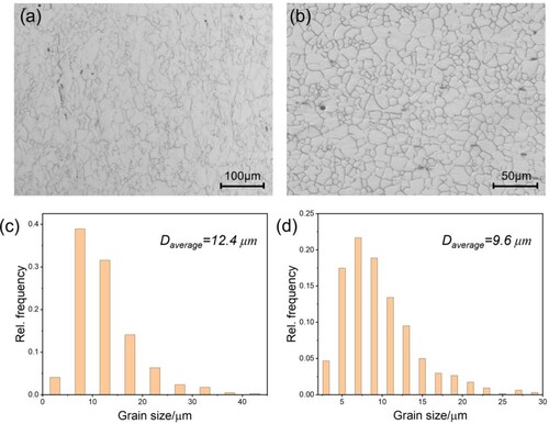
Figure 2. Photographs of the (a) spherical stir tool and (b) plane stir tool and the FS-SMATed (c,d) pure Mg plates and (e,f) AZ31 plates processed by (c,e) spherical stir tool and (d,f) plane stir tool.
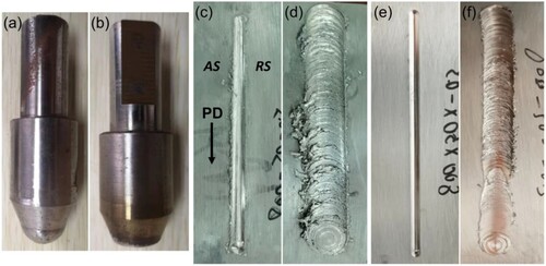
Figure 3. Macro-morphology of FS-SMATed pure Mg plates processed by (a) spherical stir tool and (b) plane stir tool and (c) the magnified morphology of the rectangle in (a).
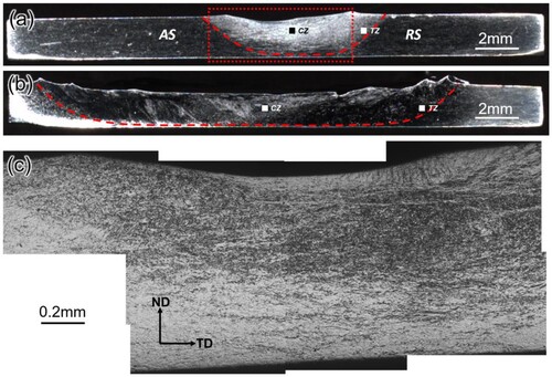
Figure 4. Microstructure of the FS-SMATed pure Mg plate using the (a,b) spherical stir tool and (c,d) plane stir tool in the (a,c) center zone and (b,d) transition zone.
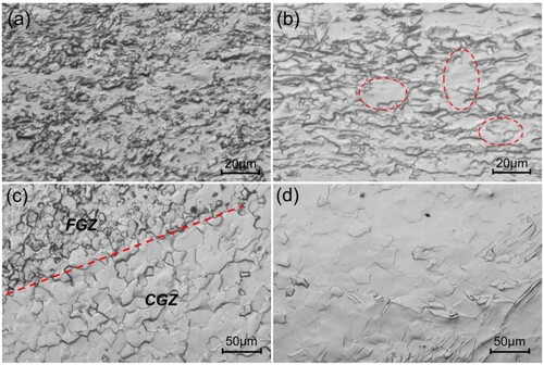
Figure 5. Macro-morphology of the FS-SMATed AZ31 Mg alloys plates processed by (a) spherical stir tool and (b) plane stir tool.
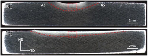
Figure 6. Microstructure in (a) the rectangular box in (a) and the typical microstructure in (b) zone-b, (c) zone-c and (d) zone-d in Figure6a and the magnified microstructure of (e) (d) and (f) (b).
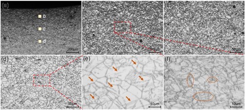
Figure 7. (a) Inverse pole figure (IPF) map and (b) related misorientation distribution in zone-d in (a). Misorientation distribution along (c) line 1 (L1) and (d) line 2 (L2) in (a).
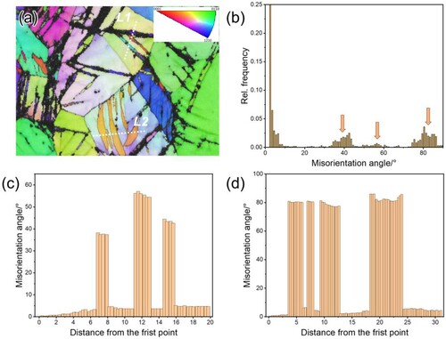
Figure 8. Microstructure in (a) the rectangular box in (b) and typical microstructure in (b) zone-b, (c) zone-c and (d) zone-d.
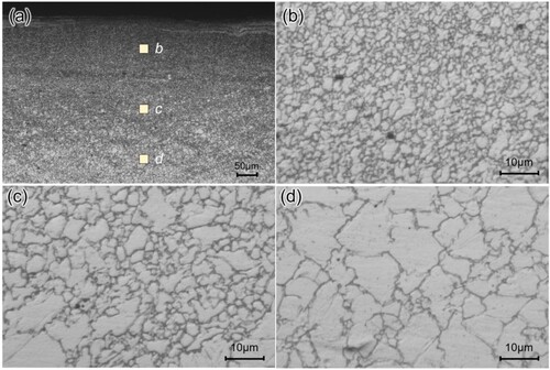
Figure 9. Micro-hardness distribution along the deformation zone for (a) pure Mg plate and (b) AZ31 Mg alloy plate after FS-SMAT with spherical and plane stir tool.
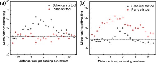
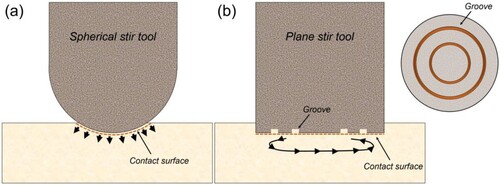
Figure 10. Schematic showing the FS-SMAT using (a) a spherical stir tool and (b) a plane stir tool.