Figures & data
Figure 1. Carbide inserts used in the present work.
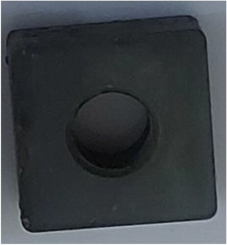
Table 1. Chemical composition for carbide tool.
Figure 2. Microstructure image for carbide cutting insert.
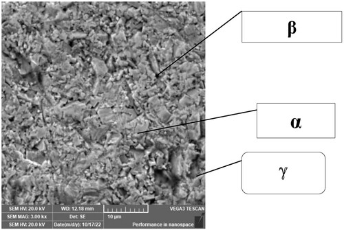
Figure 3. XRD Pattern of (a) carbide cutting tool, (b) 8YSZcoating, (c) 15 YZS coating.
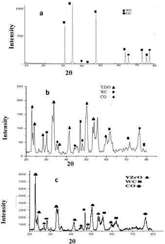
Figure 4. FESEM image of a multilayer coating (YSZ) on carbide insert: (a) 8YSZ 100000 Mag., (b) 8YSZ 25000 Mag., (c) 15YSZ 100000 Mag., (d) 15YSZ 25000 Mag.
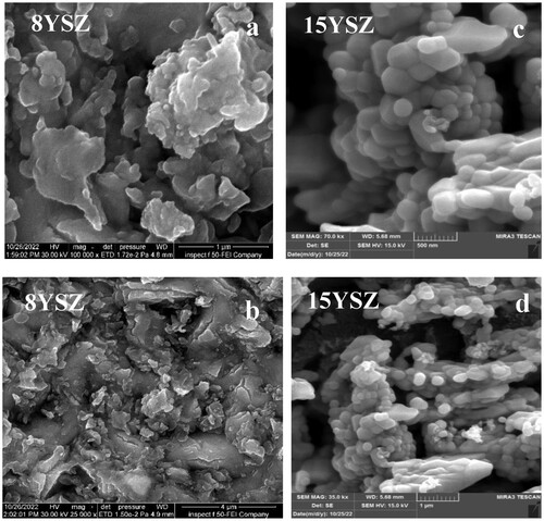
Figure 5. (a) FESEM image of coating 8YSZ on carbide insert by Sol_ gel, (b) FESEM image of 8YSZ thin film on carbide insert by Electrostatic Spray coating [Citation18].
![Figure 5. (a) FESEM image of coating 8YSZ on carbide insert by Sol_ gel, (b) FESEM image of 8YSZ thin film on carbide insert by Electrostatic Spray coating [Citation18].](/cms/asset/ca62ca81-2ff2-4a1a-9572-7b75c9761775/thts_a_2331865_f0005_ob.jpg)
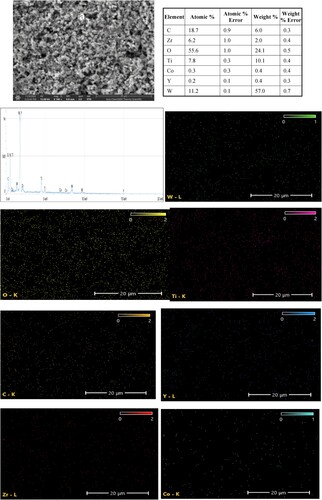

Figure 7. (a): FESEM image of coating 8YSZ on carbide insert by Sol_ gel, (b) FESEM image of 15YSZ thin film on carbide insert.
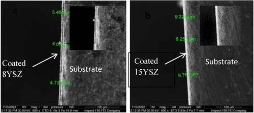
Figure 8. Coefficient of thermal expansion, (A) carbide cutting tool, (B) 8YSZ, (C) 15YSZ.
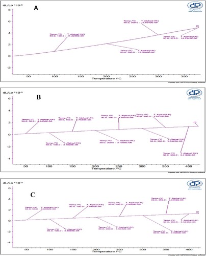
Figure 9. Transient graph of thermal conductivity of uncoated, TiO2/8YSZ coated and TiO2/15YSZ coated inserts.
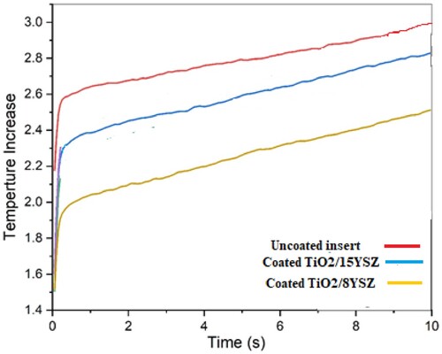
Figure 10. The micro hardness of uncoated insert and different coatings, and the images of indents produced on the surface of uncoated inserts and different coatings. (Please put the sizes corresponding to the scale bars on the images).
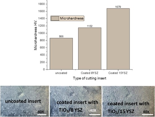
Figure 11. SEM images of the scratched (a) TiO2/ 8YSZ and (b) TiO2/15 YSZ coatings.
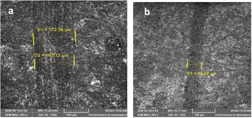
Table 2. Mechanical qualities of the coating.
Figure 12. Coefficient of friction versus time of uncoated insert and the inserts coated by TiO2/8YSZ and TiO2/15YSZ coatings respectively.
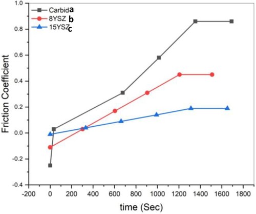
Figure 13. Wear track SEM micrographs of (a): uncoated inserts, (b): coated insert (8 YSZ), (c):coated insert (15 YSZ).
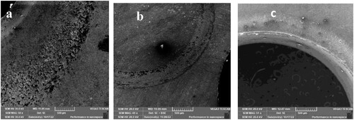
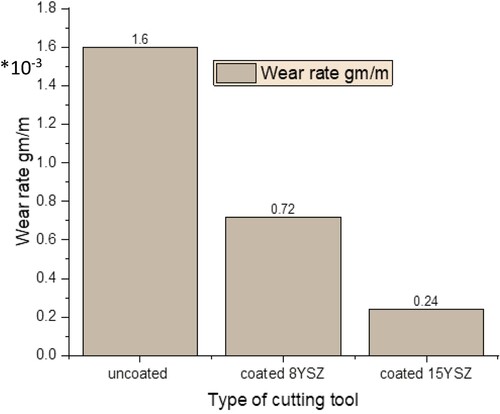
Figure 14. Wear rate of the uncoated and coated inserts.